Open-end spinning frame

A technology of open-end spinning and rotors, which is applied to spinning machines, open-end spinning machines, continuous winding spinning machines, etc., which can solve the problem of accidental opening of the swing casing, the tightness of the swing casing and the rotor casing. Reassurance, etc.

Inactive Publication Date: 2003-10-08
MASCHINENFABRIK RIETER AG
View PDF2 Cites 6 Cited by
  • Summary
  • Abstract
  • Description
  • Claims
  • Application Information

AI Technical Summary

Problems solved by technology

In this way, the tightness between the swing housing and the rotor housing is no longer guaranteed, and the second is that it is possible to accidentally open the swing housing

Method used


Image

  • Open-end spinning frame
  • Open-end spinning frame

Examples


Embodiment Construction

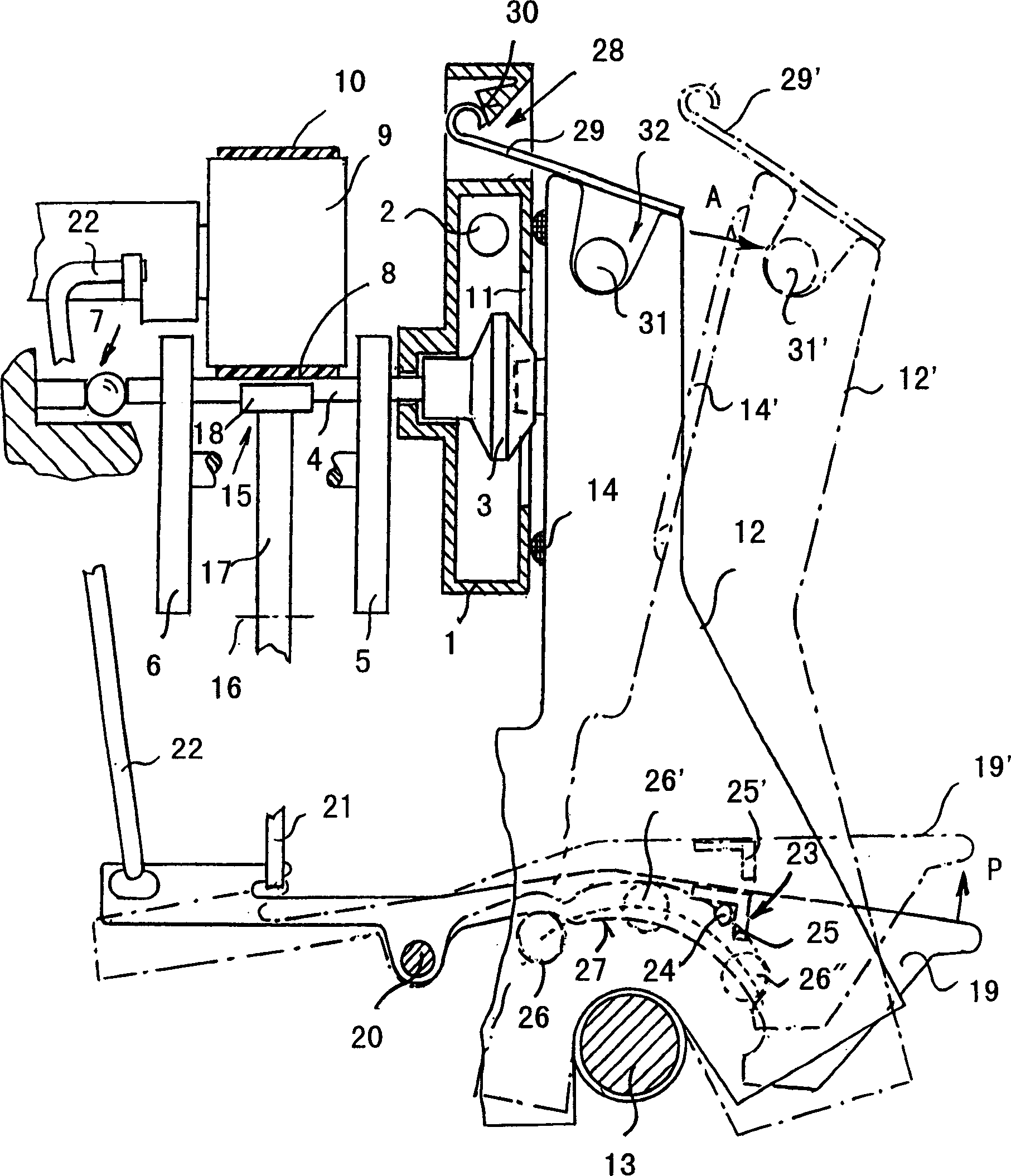
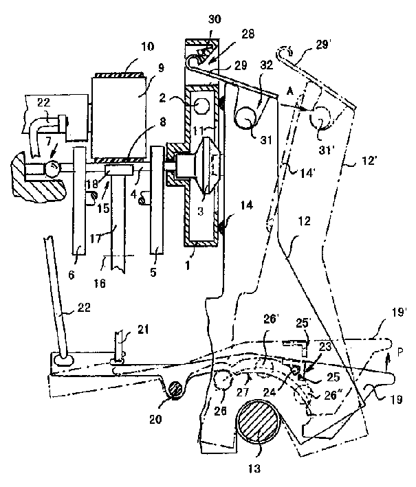
[0007] The device comprises a rotor cup housing 1 under negative pressure, which is connected to a vacuum source not shown in the figure by means of a negative pressure connecting pipe 2 . During production, a rotor 3 rotates inside the rotor housing 1, and the rotor is supported and driven outside the rotor housing 1. For this purpose, a rotor shaft 4 of the rotor 3 extends through the rear wall of the rotor housing 1 .

[0008] In a known manner, a pair of support discs 5 and 6 serve as radial bearings for the rotor shaft 4, while the rotor 3 is fixed axially in its operating position by means of a vertical thrust bearing 7. The rotor shaft 4 is driven by a tangential drive belt 8 running longitudinally of the machine, which is pressed onto the rotor shaft 4 via each pressure roller 9 . The pressure roller 9 simultaneously serves as a guide for the return run 10 of the tangential drive belt 8 .

[0009] For installation and maintenance, the rotor housing 1 is provided with...


PUM


Abstract

The air spinning device has a rotor housing under negative pressure and a rotating rotor inside the housing. In order to expose the rotor, a swivel housing is provided that can be swiveled away from the rotor housing, which rests tightly against the rotor housing during production. With the swivel housing closed, the rotor can be stopped by a brake lever with rotor brake. A form-fit locking device is connected to the brake lever, which ensures the closed position of the pivot housing and releases the lock by actuating the brake lever. A guide element is arranged on the pivot housing, which abuts against a guide surface on the brake lever to fix the braking position of the rotor brake when the pivot housing pivots. In addition to the form-fit locking device, a separately actuatable non-positive locking device is additionally provided. This not only achieves a good seal of the rotor housing, but also prevents an unintentional opening during braking.

Description

technical field [0001] The invention relates to an air spinning device, which is equipped with a rotor housing under negative pressure, a rotor rotating in the rotor housing, and a rotor which can be swung away from the rotor housing in order to expose the rotor , and close to the swing shell of the rotor cover during production, a rotor brake, a brake lever that can control the rotor brake when the swing shell is closed, and a brake lever that is connected to ensure the shape of the closed position of the swing shell Connected interlocking device, the unlocking of which is achieved by operating the brake lever, and a guide part arranged on the swing housing, which abuts against a brake lever on the brake lever to ensure the braking position of the rotor brake when the swing housing swings. guide surface. Background technique [0002] The prior art of such devices can be found in German laid-open patent text 25 55 059 . In this known device, although the rotor is always br...

Claims


Application Information

Patent Timeline
Patent Type & Authority Applications(China)
IPC IPC(8): D01H4/12
CPCD01H4/12
Inventor G·施塔莱克M·博歇尔特W·措特H·施佩斯
Owner MASCHINENFABRIK RIETER AG
Why Eureka
Try Eureka