Seal ring for steam turbine

A technology of steam turbine and sealing ring, applied in the field of sealing ring, can solve the problems of inconsistent force application direction and moving direction, air leakage, reduced sealing performance, etc.

Inactive Publication Date: 2003-07-30
MITSUBISHI HITACHIPOWER SYST LTD
View PDF2 Cites 0 Cited by
  • Summary
  • Abstract
  • Description
  • Claims
  • Application Information

AI Technical Summary

Problems solved by technology

Therefore, the urging direction of the spring 22 is inconsistent with the moving direction, and the end faces of the adjacent split pieces 21a, 21b, 21c, and 21d are separated from each other on the prescribed moving locus, and engaged abnormally, resulting in the so-called mutual interference phenomenon of the split pieces. Tablets may be stuck (occurrence of biting phenomenon)
[0005] Moreover, if such a stuck phenomenon occurs, the gap between the rotor and the rotating body will increase, causing air leakage, and there is a disadvantage that the sealing performance will be lowered.

Method used


Image

  • Seal ring for steam turbine
  • Seal ring for steam turbine
  • Seal ring for steam turbine

Examples


Embodiment Construction

[0015] Best Mode for Carrying Out the Invention

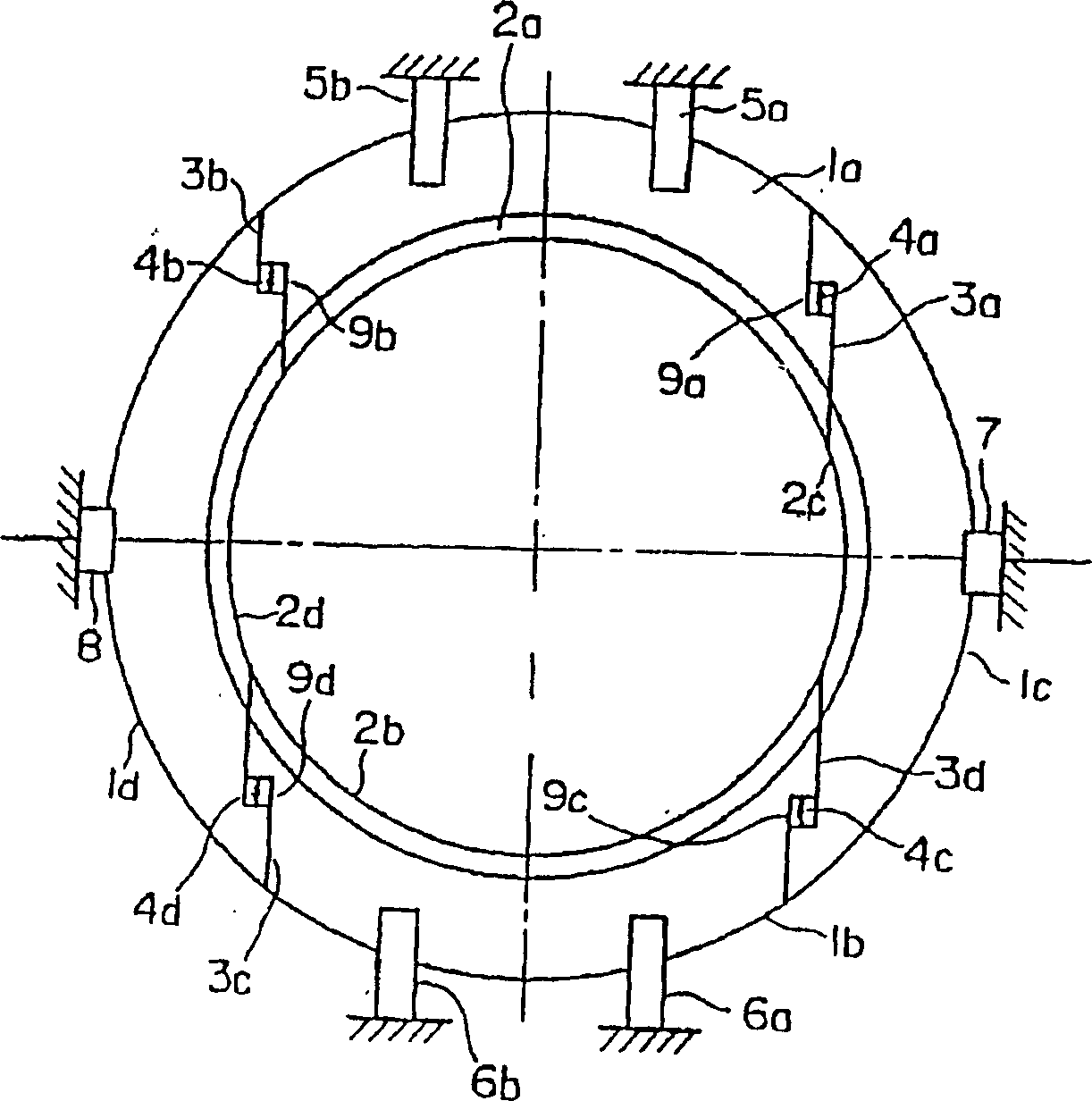
[0016] according to figure 1 A first embodiment of the present invention will be described.

[0017] figure 1 This is a diagram showing the assembled state of the seal ring in a cross-section perpendicular to the axis.

[0018] Reference numeral 1a is the upper sealing ring piece, which is located in the range of 45° left and right from the axis center to the vertical line, that is, it is arranged to be located in the range from the axis center to the upper 90° range. Reference numeral 1b is a lower sealing ring piece, which is arranged symmetrically with the above-mentioned upper sealing ring piece 1a, and is located within a range of 90° below.

[0019] The symbol 1c is the right side sealing ring piece, and the symbol 1d is the left side sealing ring piece. They are arranged in such a way that they are respectively arranged between the above-mentioned upper sealing ring piece 1a and the lower sealing ring piece 1b, and ...


PUM


Abstract

Seal ring provided between rotating portion and fixed portion in rotating machine of steam turbine and the like is improved to carry out predetermined movement accurately so as not to cause deterioration of sealing performance. Seal ring is split into upper, lower, right side and left side seal ring pieces 1a, 1b, 1c, 1d, contacting slidably with each other via split planes 3a, 3b, 3c, 3d with spaces 9a, 9b, 9c, 9d being formed in the respective split planes. Springs 4a, 4b, 4c, 4d are interposed in the spaces 9a to 9d for activation in upward and downward directions. The upper and lower seal ring pieces 1a, 1b are engaged with seal ring guides 5a, 5b and 6a, 6b and the right side and left side seal ring pieces 1c, 1d are engaged with seal ring guides 7, 8 so that all of the seal ring pieces 1a to 1d are slidable in the upward and downward directions. Further, on the respective tips of the seal ring guides 5a, 5b and 6a, 6b, spaces 10a, 10b of the upper seal ring piece 1a and spaces 10c, 10d of the lower seal ring piece 1b are formed and springs 11a, 11b, 11e, 11d are provided in the spaces 10a to 10d for activation in the upward and downward directions. The respective seal ring pieces are prevented from skirmishing with each other and the upper and lower seal ring pieces move toward the inner side at the time of load so as to make narrower the clearances between seal fins 2a, 2b and corresponding rotor surface.

Description

technical field [0001] The present invention relates to a seal ring used between rotating parts of a rotating machine such as a steam turbine. technical background [0002] In rotary machines such as steam turbines, for example, between the rotating peripheral surface divided by the front end of the moving blade and the blade holding ring, or between the inner peripheral front end of the stationary blade and the rotor surface opposite to it, in order to align the rotating part with it. A sealing comb is provided for sealing between the opposite fixing parts, and a sealing ring is provided to support the sealing comb. [0003] image 3 is a schematic diagram of a representative seal ring available at image 3 In the circumferential direction, the split pieces 21a, 21b, 21c, and 21d divided into four pieces of upper, lower, left and right are arranged, and the split pieces 21c of the left and right seal rings are arranged in the horizontal direction with the supporting parts 2...

Claims


Application Information

Patent Timeline
Patent Type & Authority Patents(China)
IPC IPC(8): F01D11/00F01D11/02F01D25/16F02C7/28F16J15/34F16J15/44
CPCF01D11/025F05B2230/604F02C7/28F05D2220/31F05B2220/301F05D2230/64F16J15/442F01D11/00
Inventor 马越龙太郎小西哲吉田善一
Owner MITSUBISHI HITACHIPOWER SYST LTD
Why Eureka
Try Eureka