
Apparatus and method for detecting imbalance in washing machines

A technology of balance detection and washing machine, applied in the control device, washing device, measuring device of washing machine, etc., can solve problems such as hindering the smooth running of washing.

Inactive Publication Date: 2003-10-15
MITSUBISHI ELECTRIC CORP +1
View PDF0 Cites 8 Cited by
  • Summary
  • Abstract
  • Description
  • Claims
  • Application Information

AI Technical Summary

Problems solved by technology

Therefore, even if the amount of unbalance is small, there is no need to stop the washing and dehydrating tank for a small displacement, and the washing and dehydrating tank will stop, hindering the smooth progress of washing operation.

Method used


Image

  • Apparatus and method for detecting imbalance in washing machines
  • Apparatus and method for detecting imbalance in washing machines
  • Apparatus and method for detecting imbalance in washing machines

Examples


Embodiment Construction

[0025] Embodiment of the invention

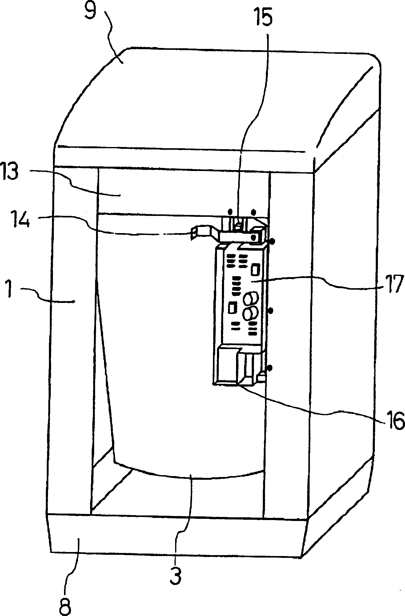
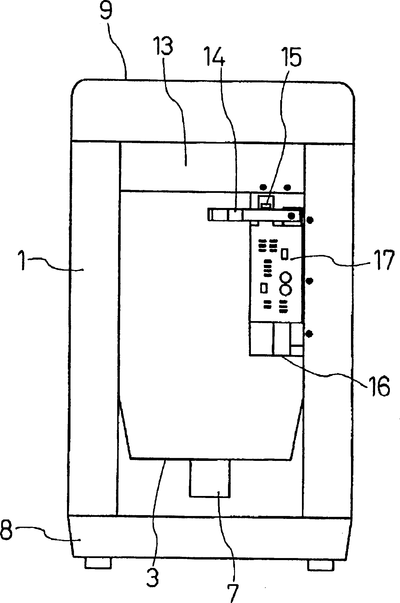
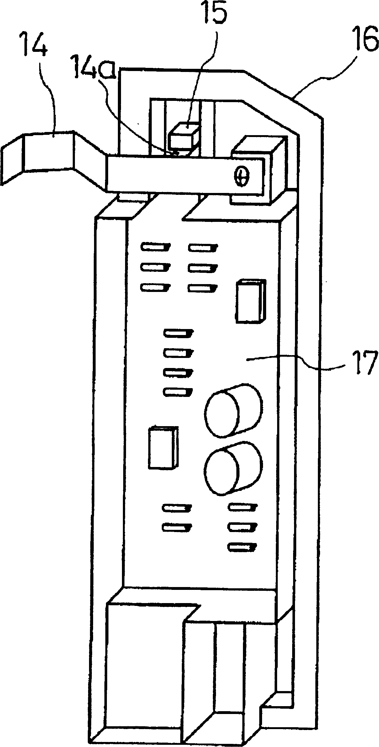
[0026] Hereinafter, embodiments of the present invention will be described in detail with reference to the drawings. figure 1 It is a perspective view of a washing machine with the unbalance detection device of the present invention with the front panel removed, figure 2 For the front view of the same as above, image 3 is a perspective view showing an embodiment of the unbalance detecting device of the washing machine of the present invention, Figure 4 It is the top view of the same, and Fig. 5 is the exploded perspective view of the same, because Figure 7 The overall configuration of the single-tub type washing machine has been described, and its detailed description is omitted here.

[0027] The unbalance detecting device of the present invention is composed of a lever 14 that is displaced by the swing of the water tank 3 and a sensor 15 that detects the displacement of the lever 14. The sensor 15 is, for example, a light circuit f...


PUM


Abstract

PROBLEM TO BE SOLVED: To obtain a device and a method for detecting an unbalance of a washing machine which reduce the number of components, simplify the structure and moreover enable stop of the rotation of a washing and dewatering tub corresponding to the amount of the unbalance, only when it is needed.SOLUTION: The washing and dewatering tub provided with a rotating blade at the bottom is disposed rotatably in a water tank 3 suspended and supported swingably in an outer box 1. In the washing machine having this constitution, the device for detecting the unbalance is disposed between the outer box 1 and the water tank 3 and fitted to a unit case 16 of a power supply unit disposed in the outer box 1.

Description

technical field [0001] The invention relates to an unbalance detection device and a detection method of a washing machine. Background technique [0002] For example, a single-cylinder fully automatic washing machine such as Figure 7 As shown, in the outer box 1 that is arranged on the bottom frame 8, a water tank 3 can be suspended freely through the anti-vibration device 2. In the water tank 3, a washing and washing machine with a rotating blade 4 at the bottom can be freely rotated. The dehydration tank 5 is equipped with the mechanism part 7 of the reduction mechanism of the motor 6 and clutches, gears, etc. as the drive mechanism at the bottom of the water tank 3. In addition, a top cover 9 is installed on the top of the outer case 1 and above the water tank 3. The top cover 9 is provided with a cover 10 which can be opened and closed freely. 11 shows the water supply tank communicated with the water supply port arranged on the top cover 9 among the figures. [0003] ...

Claims


Application Information

Patent Timeline
IPC IPC(8): D06F33/02D06F37/24D06F37/42G01M1/22
CPCD06F37/24D06F37/42D06F34/16D06F39/125D06F2103/26D06F2105/58Y02B40/00
Inventor 石川则彦及川贵裕
Owner MITSUBISHI ELECTRIC CORP
Learn More