Dual scan method of matrix display panel

A double-scanning, display panel technology, applied in the field of double-scanning, can solve the problem of strong light generated by the panel

Inactive Publication Date: 2003-10-22
LG ELECTRONICS INC
View PDF0 Cites 16 Cited by
  • Summary
  • Abstract
  • Description
  • Claims
  • Application Information

AI Technical Summary

Problems solved by technology

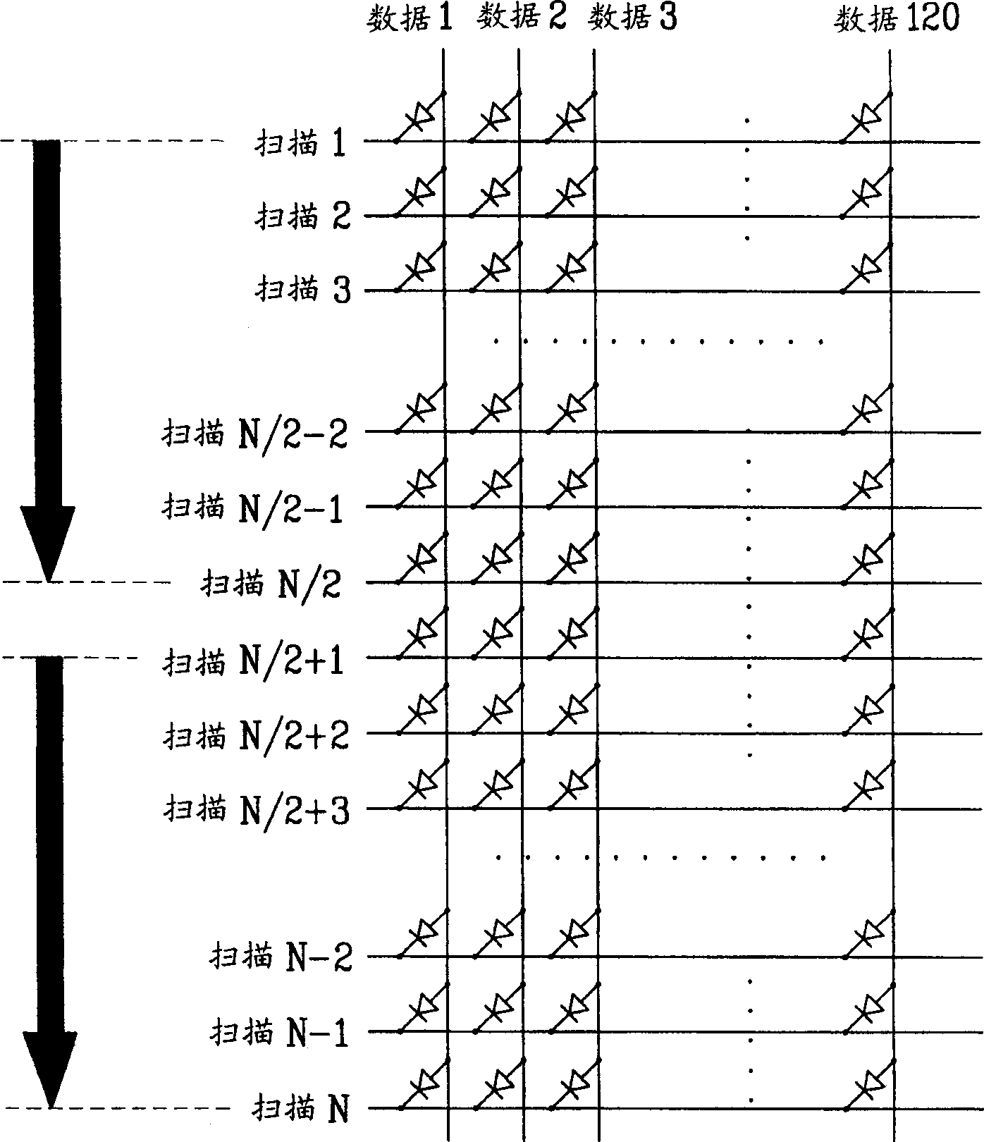
[0019] However, the above-mentioned double scan method has such a problem that the central part of the panel is momentarily brightly lit, becoming the boundary between the upper half and the lower half

Method used


Image

  • Dual scan method of matrix display panel
  • Dual scan method of matrix display panel
  • Dual scan method of matrix display panel

Examples


Embodiment Construction

[0033] Reference will now be made in detail to the preferred embodiments of the invention, examples of which are illustrated in the accompanying drawings. Wherever possible, the same reference numbers will be used throughout the drawings to refer to the same or like parts.

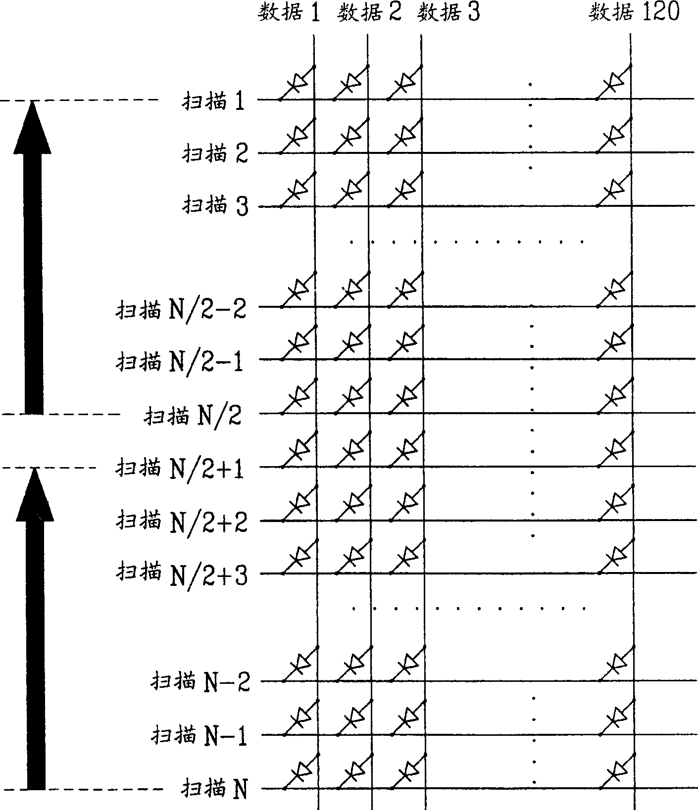
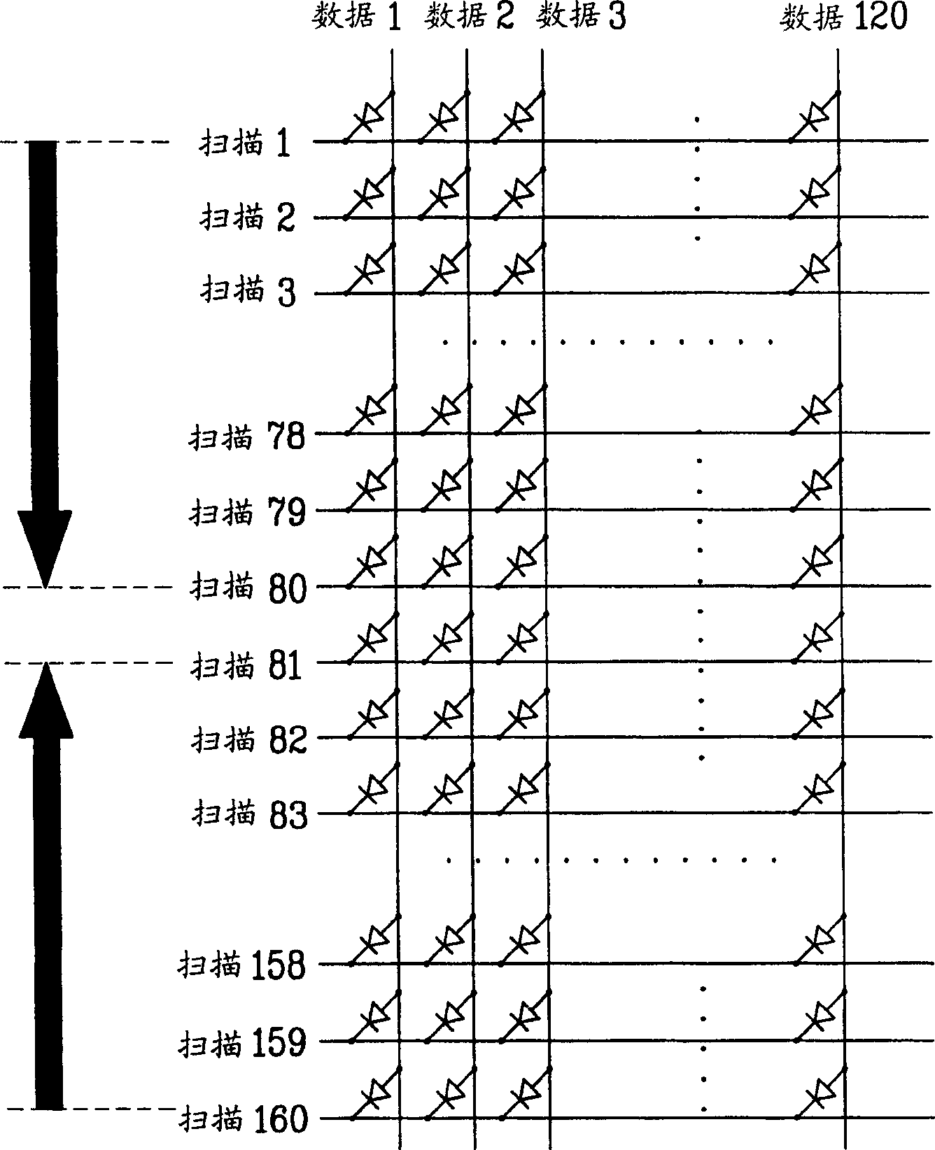
[0034] image 3 and Figure 4 Figures illustrating the dual scanning method of the passive matrix display panel according to the present invention, respectively.

[0035] image 3 and Figure 4 Each of the shown display panels has a passive matrix structure of 120 (column lines / data lines)*160 (horizontal lines / scanning lines).

[0036] image 3 and Figure 4 Each of the shown display panels is double-scanned on 80 scan lines in the upper half and 80 scan lines in the lower half.

[0037] refer to image 3 , a display panel with 160 scan lines is divided into an upper half and a lower half.

[0038] That is, the upper half includes the 1st to 80th scan lines, and the lower half includes the 81st t...


PUM


Abstract

Disclosed is a dual scan method of a display panel having M data lines and N scan lines. The present invention includes the steps of dividing the N scan lines into an upper half and a lower half; and applying current to the scan lines of the upper half and the lower half respectively to scan, wherein the scan lines of the upper half and the scan lines of the lower half are sequentially scanned to be symmetrical to each other centering on a central axis of the display panel.

Description

[0001] This application claims priority from Korean Application No. P2002-18659 filed Apr. 4, 2002, which is hereby incorporated by reference. technical field [0002] The invention relates to a display panel, in particular to a double scanning method for a display panel with a passive matrix structure. Background technique [0003] Recently, rapid development has occurred in the field of flat display panels. [0004] Specifically, the flat display panel includes a liquid crystal display (LCD), which is a main product appearing on the market to replace the cathode ray tube (CRT), which is currently the most widely used in the display field. Recently, great progress has been made in flat display panels including plasma display panels (PDPs), visible fluorescent displays (VFDs), field emission displays (FEDs), light emitting diodes (LEDs), electroluminescence (ELs), and the like. [0005] Such a flat display panel requires a simple manufacturing process while having high visi...

Claims


Application Information

Patent Timeline
Patent Type & Authority Applications(China)
IPC IPC(8): H01L51/50G09G3/20G09G3/30G09G3/32
CPCG09G3/20G09G2310/0205G09G3/3216G09G2310/0221G09G2310/0283G09G3/30
Inventor 金学洙金正培南荣熙金昌镇
Owner LG ELECTRONICS INC
Why Eureka
Try Eureka