LED (Light-Emitting Diode) lamp tube with large light flux and large light-emitting angle and manufacturing method thereof

A technology of LED tube and light emitting angle, applied in the field of LED tube, can solve the problems of increasing the power consumption of fluorescent tube, high manufacturing cost, increasing possibility of failure, etc., and achieve the effect of improving system reliability and system repair ability

Inactive Publication Date: 2013-12-11
彭雯
View PDF5 Cites 14 Cited by
  • Summary
  • Abstract
  • Description
  • Claims
  • Application Information

AI Technical Summary

Problems solved by technology

The first method has limited improvement in heat dissipation. The second method increases the power consumption of fluorescent tubes and has high manufacturing costs. In addition, the possibility of failure during use increases. Although the third method solves the heat dissipation problem better, However, no effective improvement has been made to the propagation quality of light integrated with LED illuminants
Another kind of LED lamp tube adopts the heat-dissipating and heat-transfer aluminum profile to be built into the inner wall of the glass cover tube along the axial direction, so that the LED luminous body directly fits closely with the aluminum

Method used


Image

  • LED (Light-Emitting Diode) lamp tube with large light flux and large light-emitting angle and manufacturing method thereof
  • LED (Light-Emitting Diode) lamp tube with large light flux and large light-emitting angle and manufacturing method thereof
  • LED (Light-Emitting Diode) lamp tube with large light flux and large light-emitting angle and manufacturing method thereof

Examples


Example Embodiment

[0019] The specific implementation method comprises the following steps:

[0020] a. Put the COMMB-LED light source mold strip completed by solid crystal, wire bonding, dispensing and external lead electrode tinning into the serial-parallel tooling, and perform serial-parallel soldering connection;

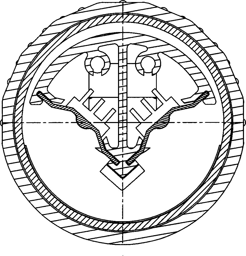
[0021] b. Use the COMMB-LED light source mold strip to install it into the COMMB-LED light source mold strip embedding groove on the two symmetrical slopes of the heat-conducting and heat-transfer aluminum profile of the V-shaped structure;

[0022] c. Install the diffusion film axially into the glass tube along the inner wall of the light-emitting end of the glass tube;

[0023] d. Put the combination of the V-shaped heat-dissipating heat-transfer aluminum profile and the COMMB-LED light source assembly into the glass tube;

[0024] e. After injecting flexible hot-melt colloid into the rubber ring groove of the insulating connecting sleeve on the supporting part along the circum...

Example Embodiment

specific embodiment

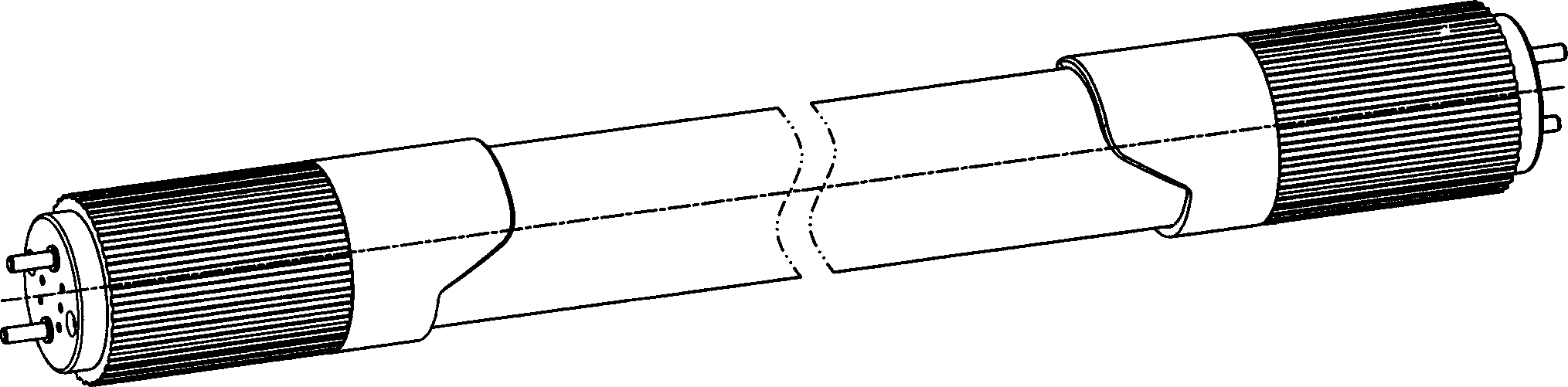
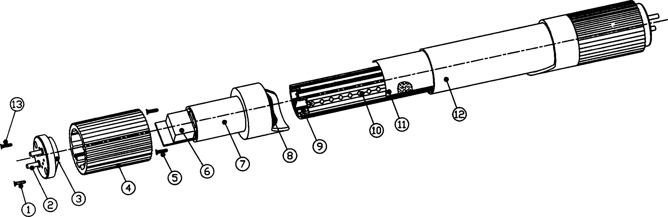
[0032] like figure 1 , 2 As shown, a LED lamp tube with large luminous flux and large light output angle includes: 1. End cap locking screws for connecting the external copper post wiring cover of the LED fluorescent lamp tube with the aluminum shell cap; 2. External copper post, which is introduced Realize the rigid connection between the lamp tube and the lamp frame at the same time as the mains; 3. The external copper column connection cover is used as the support of the external copper column in the LED fluorescent tube and the axial cover of the lamp tube; 4. The aluminum shell cover head, Used as the heat sink of the constant current power supply of the COMMB-LED light source component and the connecting piece of the plastic transition sleeve; 5. The set screw of the transition sleeve is used to complete the rigidity of the plastic transition sleeve, the aluminum shell cover head and the external copper column wiring cover Connection; 6. Constant c...


PUM

PropertyMeasurementUnit
Beam angleaaaaaaaaaa

Abstract

The invention relates to an LED (Light-Emitting Diode) lamp tube with large light flux and a large light-emitting angle. The LED lamp tube is provided with an insulated connecting sleeve which introduces a power supply to the electricity supply part of a COMMB-LED light source assembly and the heat dissipating and transferring aluminum profile support frame part of a V-shaped structure; the combined body of the heat dissipating and transferring aluminum profile of the V-shaped structure and the COMMB-LED light source assembly is arranged in a glass lamp tube. The LED lamp tube is characterized in that the heat conducting and transferring aluminum profile of the V-shaped structure is arranged in the glass lamp tube of the LED lamp tube along the length direction of the lamp tube; the COMMB-LED light source assembly is arranged on two symmetrical inclined surfaces of the heat conducting and transferring aluminum profile of the V-shaped structure and closely contact with the heat conducting and transferring aluminum profile in an adhering way; both ends of the lamp tube is provided with constant current power supplies; a diffusion membrane or a fluorescent powder adhesive tape which realizes light uniformity, different color temperature and color developing indexes is arranged on the inner wall of the glass tube positioned in the light-emitting direction of the COMMB-LED light source assembly.

Description

technical field [0001] The invention relates to an LED lamp tube with an LED as a luminous body, in particular to an LED lamp tube with a large luminous flux and a large light output angle using a COMMB-LED light source assembly as a light source. Background technique [0002] The current LED lamp tubes mostly use heat-conducting glue to stick a single LED lamp bead as a light-emitting body to the supporting plane of the heat-dissipating aluminum profile. The aluminum profile is seamlessly buckled with the PC cover, and the light-emitting body is mostly made of PCB. The printed circuit on the board is used as the circuit connection board of the independent lamp bead, and the white light-emitting LED is connected in series through the printed circuit on the PCB board to form a low-voltage module and then connected to the constant current power supply controller. As far as the existing LED light tubes are concerned, whether the illuminant uses a rectangular electrode in-line l...

Claims


Application Information

Patent Timeline
IPC IPC(8): F21S2/00F21V23/00F21V29/00F21Y101/02F21V29/503F21V29/70
Inventor 彭雯
Owner 彭雯
Why Eureka
Try Eureka