Method for coating active component cellular carrier

A honeycomb carrier, active component technology, applied in chemical instruments and methods, catalyst activation/preparation, physical/chemical process catalysts, etc., can solve problems such as uneven coating, and achieve the effect of uniform coating

Inactive Publication Date: 2003-12-17
CHINA PETROLEUM & CHEM CORP +1
View PDF2 Cites 15 Cited by
  • Summary
  • Abstract
  • Description
  • Claims
  • Application Information

AI Technical Summary

Problems solved by technology

[0005] The purpose of the present invention is to overcome the shortcomings of prior art coating une

Method used


Image

  • Method for coating active component cellular carrier
  • Method for coating active component cellular carrier
  • Method for coating active component cellular carrier

Examples


example 1

[0026] This example illustrates the method provided by the invention.

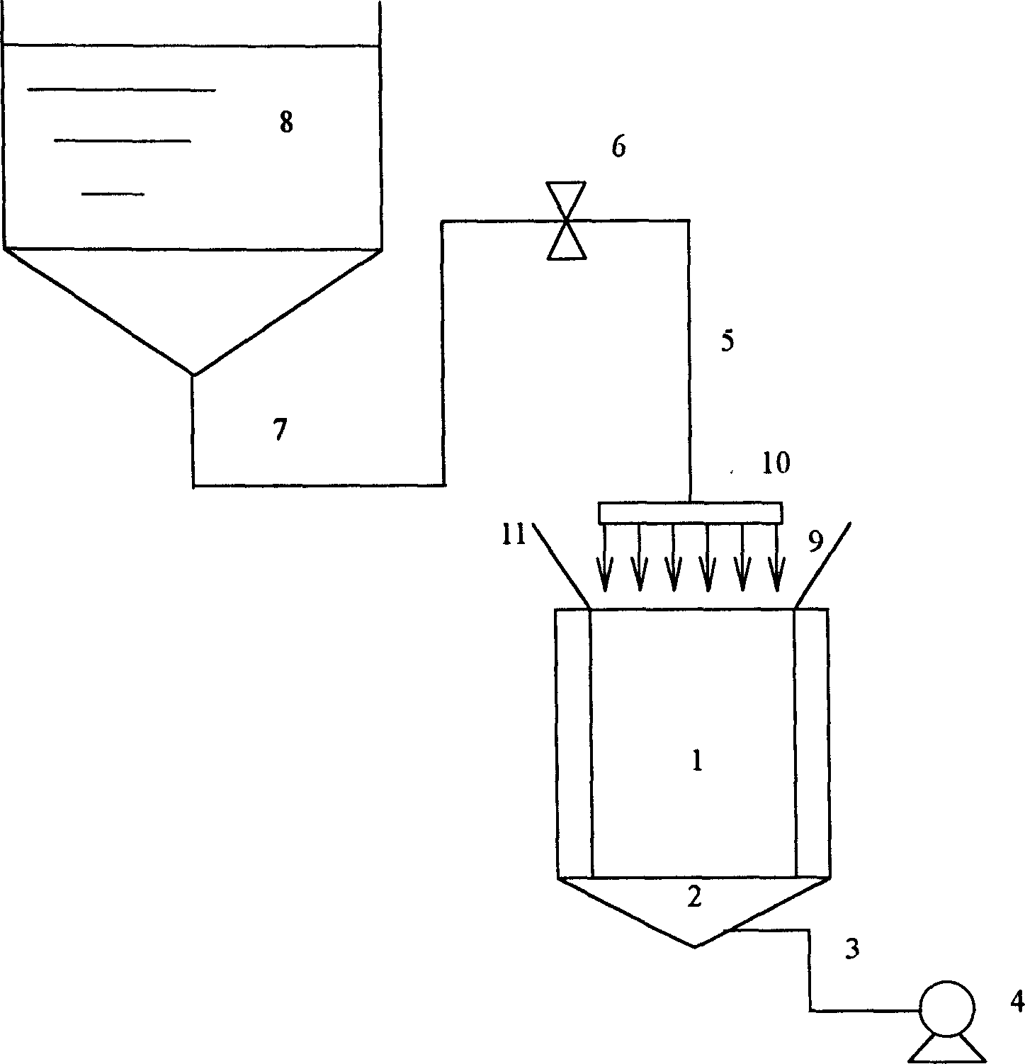
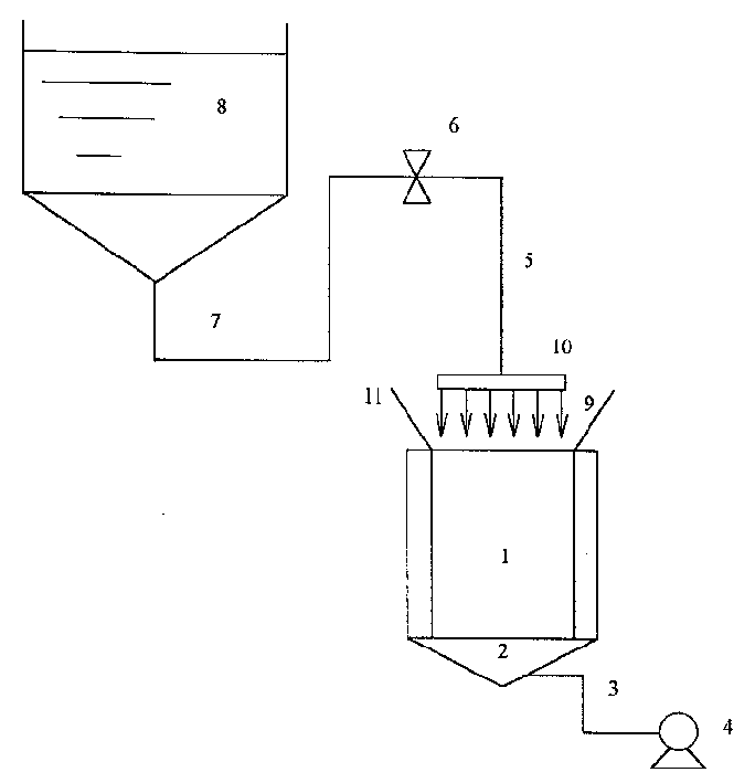
[0027] Such as figure 1 As shown, (1) the honeycomb carrier 1 with particle trapping function is placed vertically, and the space 2 at the lower end of the carrier 1 is sealed. The carrier 1 is a cylindrical ceramic carrier with a weight of 1312 grams and a cross-sectional area of ​​162.24 cm 2 , the height is 15.24 cm, and the number of pores on the cross-section is 15.5 pores / cm 2 , the cross-sectional area of ​​the square air hole is 16.0mm 2 (the side length is 4.0 millimeters), the volume of the carrier is 2473 milliliters, each pore is blocked at one end, and the water pore volume is 494.6 milliliters.

[0028] Turn on the vacuum pump 4, vacuumize the confined space 2 through the pipeline 3, and when the pressure reaches 70 kPa, open the valve 6, the slurry 9 is ejected from the nozzle 10, and the slurry 9 enters from the storage tank 8 through the pipeline 7, valve 6 and pipeline 5 Nozzle10.

...


PUM


Abstract

A process for coating the active component on the cellular carrier having particles capturing function includes such steps as standing the cellular carrier vertically, spraying the active component slurry on its top end while applying vacuum (0-85 KPa) to its bottom end, turning said cellular carrier over by 180 deg., repeating above steps, turning the carrier over by 180 deg to release the excess slurry, and drying.

Description

technical field [0001] The invention relates to a method for coating active components on a honeycomb support. Background technique [0002] Diesel vehicle exhaust purification catalyst is an important means to deal with modern diesel vehicle exhaust and make its emissions meet environmental protection requirements. The diesel vehicle exhaust gas purification catalyst is similar to the automobile exhaust gas purification catalyst in that both are composed of a honeycomb carrier and active components coated on the carrier, and the honeycomb carrier contains many parallel pores. The difference is that the cells contained in the honeycomb carrier of the automobile exhaust gas purification catalyst are open at both ends, and the hole density on the cross section is 46.5-186.0 holes / cm 2 , the cross-sectional area of ​​each hole is 0.91-1.72mm 2 . The honeycomb carrier of the diesel vehicle exhaust gas purification catalyst contains each pore that has ...

Claims


Application Information

Patent Timeline
IPC IPC(8): B01J37/02
Inventor 邵潜达志坚贺振富景振华段启伟李燕秋李晓燕沈宁元李阳罗珍蒋文斌陈蓓艳
Owner CHINA PETROLEUM & CHEM CORP
Why Eureka
Try Eureka