Method and device for realizing dynamic tunable chatter by using Mach-Zehnder modulator

A modulator and dynamic technology, applied in instruments, optics, electrical components, etc., can solve the problem that the MZ modulator cannot perform phase modulation, etc., to achieve the effect of intensity modulation and phase modulation, and improve the transmission performance of the system

Inactive Publication Date: 2003-12-24
HUAWEI TECH CO LTD
View PDF0 Cites 3 Cited by
  • Summary
  • Abstract
  • Description
  • Claims
  • Application Information

AI Technical Summary

Problems solved by technology

[0006] The purpose of the present invention is to solve the problem that the phase modulation cannot be performed while using the MZ modulator for intensity modulation in the current optical fiber transmission system, and propose a method for using the MZ modulator to realize the dynamic adjustment of the chirp, that is, in Appropriate phase modulation is added to the intensity modulation to improve the system transmission performance of the optical fiber transmission system

Method used


Image

  • Method and device for realizing dynamic tunable chatter by using Mach-Zehnder modulator
  • Method and device for realizing dynamic tunable chatter by using Mach-Zehnder modulator
  • Method and device for realizing dynamic tunable chatter by using Mach-Zehnder modulator

Examples


Embodiment Construction

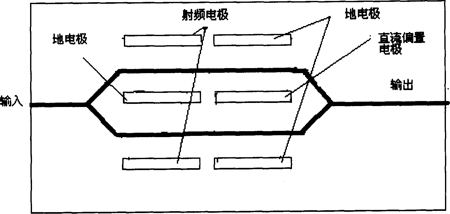
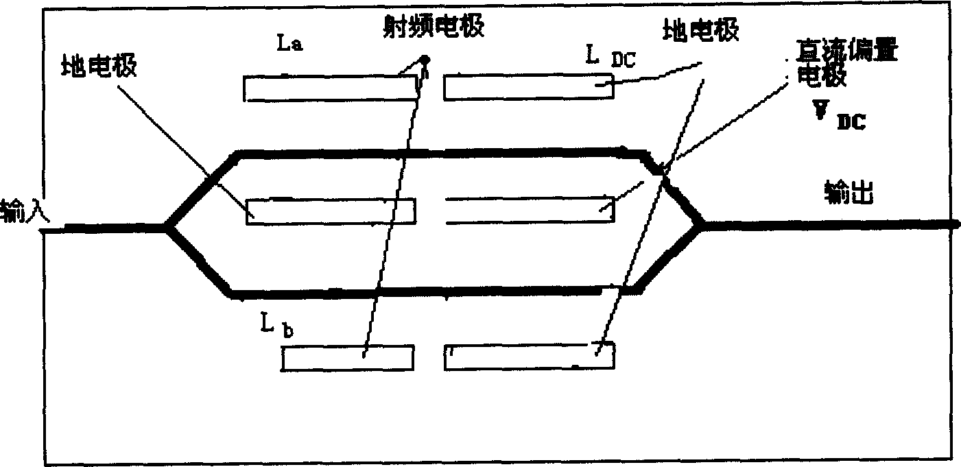
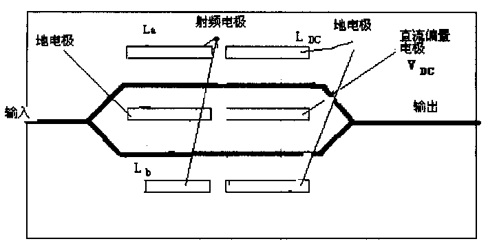
[0014] According to the modulation principle of the MZ modulator described above, if chirp is required, it must be term is non-zero and not a constant. Since the DC bias voltage has no effect on the size of the chirp, only the additional phase ψ caused by the RF electrode needs to be considered a RF and ψ b RF The resulting chirp. The magnitude of the chirp coefficient a can use the absolute value of the following expression, and its sign needs to consider the position of the DC bias point. a = ψ a RF + ψ b RF ψ a RF - ψ b RF

[0015] if ψ a RF = ...


PUM


Abstract

MZ modulator is in the structure of electrodes with common ground. The chatter magnitude can be adjusted by changing the radio frequency voltage on the radio frequency electrode of the MZ modulator. The magnitude of chatter coefficient is equal to the ration between the sum of the phase shift (psi aRF +psi bRF) and the difference of the phase shift (psi aRF -psi bRF) caused by the radio frequency voltages at upper and lower branches. The invented method can control the generated chatter magnitude simply and accurately by adjusting the drive voltage, realizing intensity modulation and phase modulation so as to improve the system transmission performances of the optical fiber transmission system.

Description

technical field [0001] The invention relates to the field of optical fiber communication, in particular to a method and device for intensity modulation and phase modulation in an optical fiber transmission system. Background technique [0002] Mach-Zehnder (Mach-Zehnder) modulator, also known as MZ modulator, is a key device for realizing high-speed data electro-optical conversion in optical fiber transmission system. From the perspective of electrode position, MZ modulators usually have two structures: a common RF electrode structure and a common ground electrode structure. The common RF electrode structure refers to the use of two ground electrodes and one RF electrode, that is, the RF electrode is in the middle of the two waveguides and the two ground electrodes are on both sides of the waveguide. The structure of the common ground electrode is the opposite: two radio frequency electrodes and one ground electrode are used, that is, the ground electrode is in the middle o...

Claims


Application Information

Patent Timeline
Patent Type & Authority Applications(China)
IPC IPC(8): G02F1/35H04B10/516
Inventor 余力
Owner HUAWEI TECH CO LTD
Why Eureka
Try Eureka