Supercharge Your Innovation With Domain-Expert AI Agents!

Sphygmomanometer

A sphygmomanometer and pressure technology, applied in vascular assessment, cardiac catheterization, etc., can solve problems such as prolonged measurement time

Inactive Publication Date: 2003-12-24
CITIZEN WATCH CO LTD
View PDF0 Cites 0 Cited by
  • Summary
  • Abstract
  • Description
  • Claims
  • Application Information

AI Technical Summary

Problems solved by technology

[0021] The object of the present invention is to improve the above-mentioned problems existing in the existing sphygmomanometer, that is, to improve the subject's excessive pressurization pressure in the blood pressure measurement after the second time, or to reduce the measurement time due to repressurization. Extended Questions for Topics

Method used


Image

  • Sphygmomanometer
  • Sphygmomanometer
  • Sphygmomanometer

Examples


Embodiment Construction

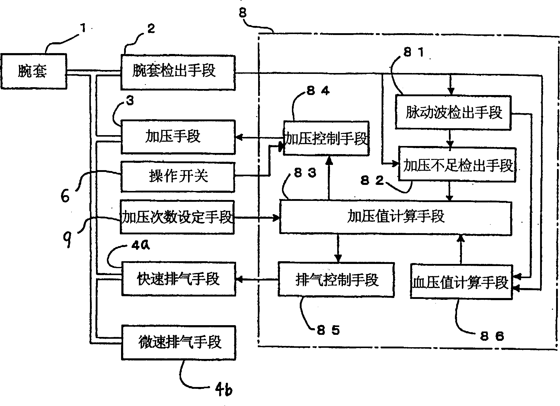
[0030] The sphygmomanometer of the present invention is used figure 1 The functional block diagram representation.

[0031] The sphygmomanometer consists of a wrist cuff 1, a wrist cuff pressure detection means 2 connected to the wrist cuff 1 through an air hose 1b, a pressurization means 3, a fast exhaust means 4a and a slow exhaust means 4b, and these means 2, 3 and 4a connected to the control section 8 constitutes. This sphygmomanometer is also provided with an operation switch 6 for sending instructions to the control unit 8 .

[0032] In addition, the control section 8 is selectively connected to pressurization number setting means 9 .

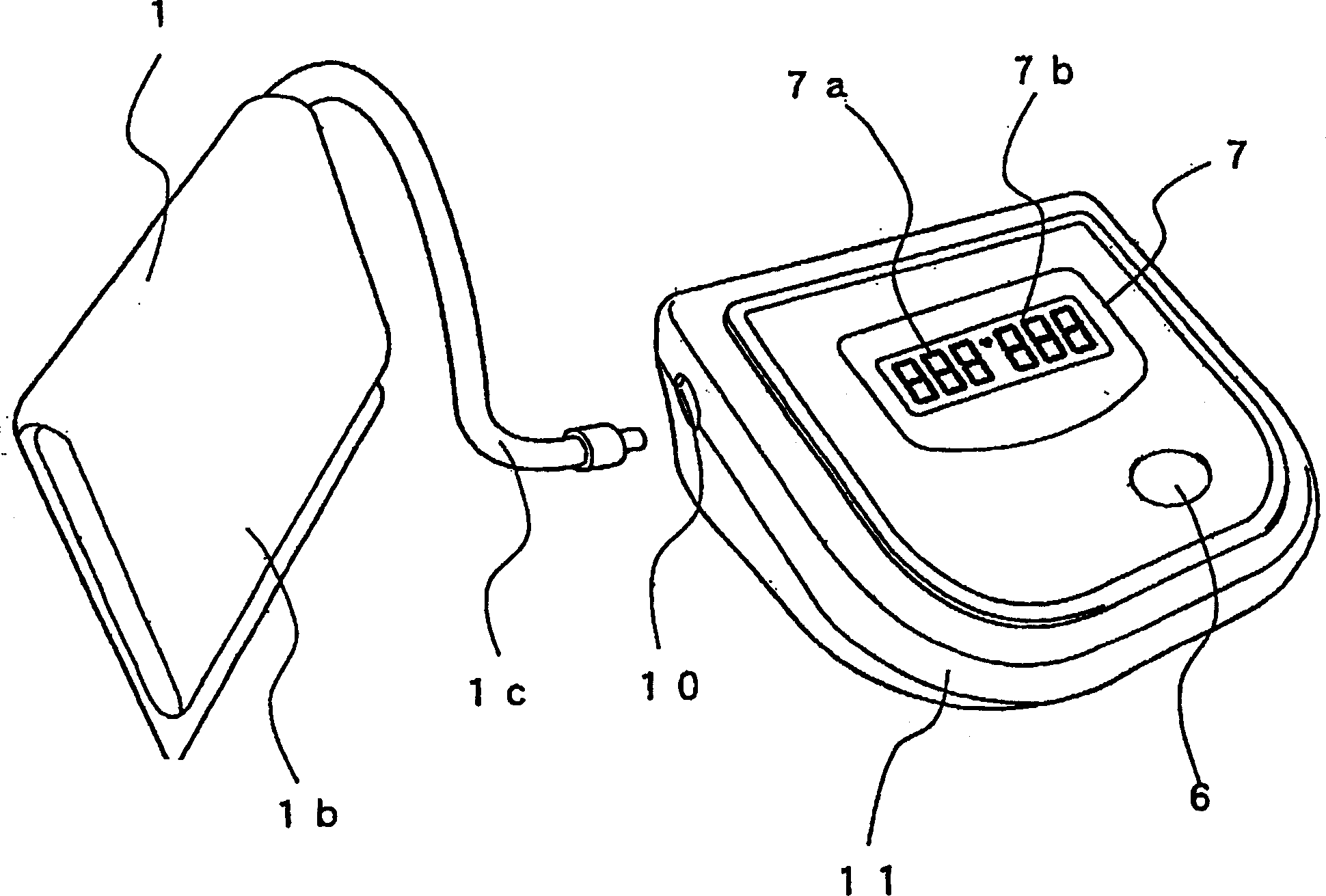
[0033] Wristband 1, such as figure 2As shown, it is a bag used to pressurize the subject's wrist and tighten the blood vessels. The pressurizing means 3 is specifically a pressurizing pump, which delivers air to the wristband 1 to exert pressure on the wristband. Quick exhaust means 4a is to release the pressurized air in the wrist...


PUM


Abstract

A sphygmomanometer, wherein the mode of pressurization on the cuff for measuring a blood pressure is varied according to whether a time for continuously pressing an operating switch (6) is longer or shorter than a set time, and whether the operating switch (6) is released before the blood pressure reaches a preset pressurizing value or at any time point after the blood pressure exceeds the set pressurizing value.

Description

technical field [0001] The invention relates to an electronic sphygmomanometer which determines the blood pressure value by detecting the pulse pressure of each pulse superimposed on the cuff pressure (Cuff pressure). Especially a sphygmomanometer that detects the pulse wave and determines the blood pressure value during the gradual decompression process once the wrist cuff is pressurized. Background technique [0002] When blood pressure is measured several times with a sphygmomanometer, it is known to set the pressure value of the wrist cuff based on the highest blood pressure value measured last time at the time of the second and subsequent measurements. [0003] attached Figure 10A And attached Figure 10B , is a graph showing the change of pressure in the wrist cuff (cuff pressure) and pulse wave data during blood pressure measurement, with Figure 11 It is a time chart showing the method of pressurizing the wrist cuff with the existing sphygmomanometer to measure bl...

Claims


Application Information

Patent Timeline
IPC IPC(8): A61B5/0225
CPCA61B5/0225
Inventor 伊藤清柴田浩明新田达夫
Owner CITIZEN WATCH CO LTD
Features
  • R&D
  • Intellectual Property
  • Life Sciences
  • Materials
  • Tech Scout
  • Unparalleled Data Quality
  • Higher Quality Content
  • 60% Fewer Hallucinations
Learn More