

Valve, gas control device, and sphygmomanometer
a gas control device and valve body technology, applied in the direction of engine diaphragms, diaphragm valves, angiography, etc., can solve the problems of difficult to join large containers, inability to have a region for firmly joining the cuff, etc., and achieve a wide joining area and reduce the profile
- Summary
- Abstract
- Description
- Claims
- Application Information
AI Technical Summary
Benefits of technology
Problems solved by technology
Method used
Image

Examples
first embodiment
[0034]A gas control device 100 according to the present disclosure is described below.
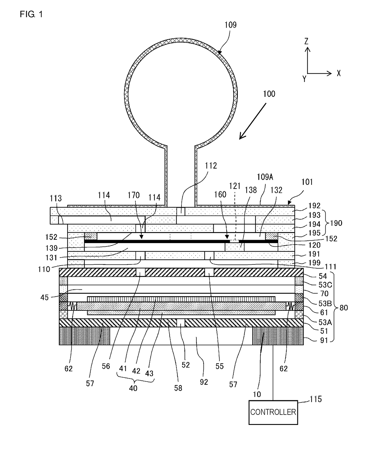
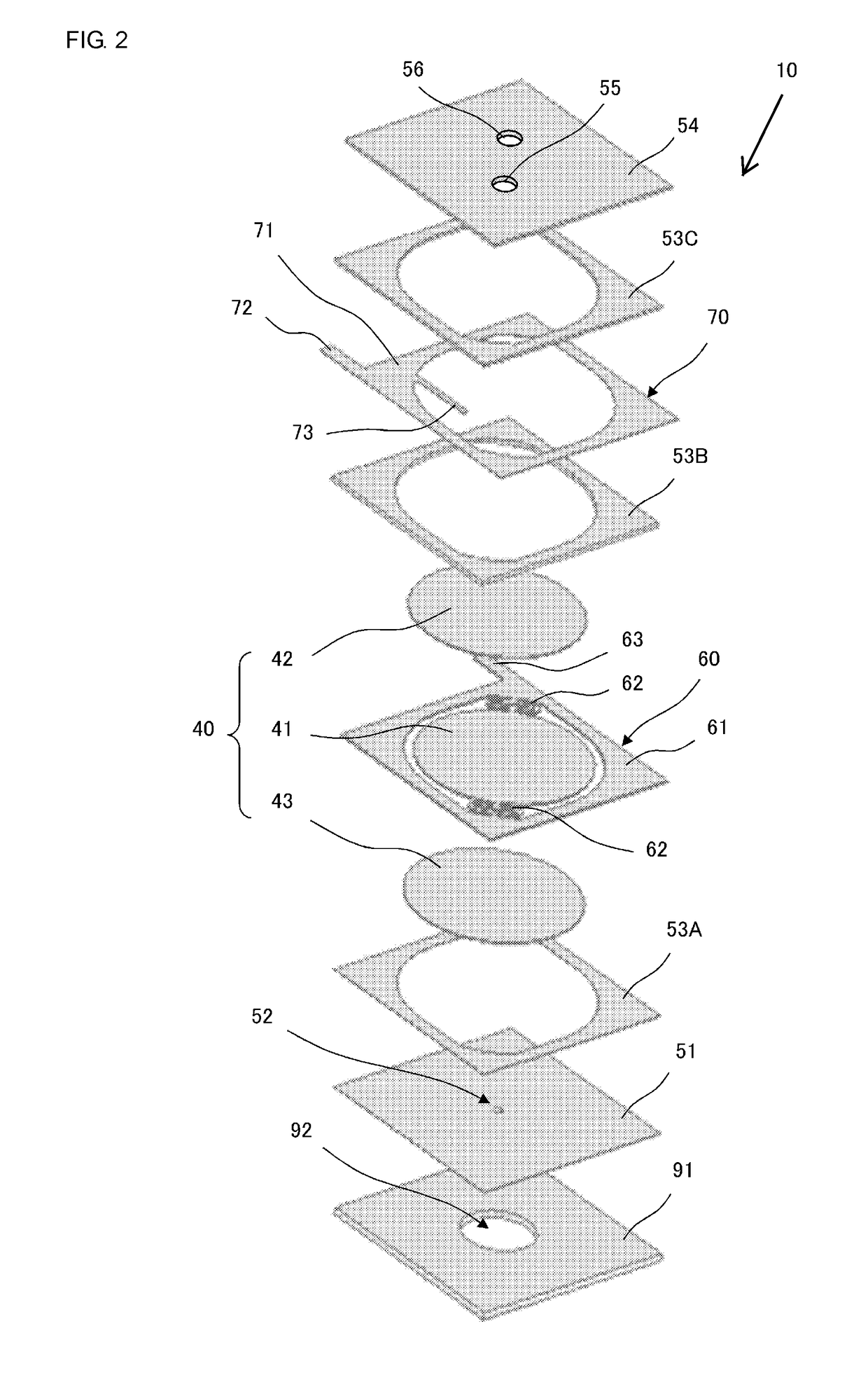
[0035]FIG. 1 is a cross-sectional view of a main portion of the gas control device 100 according to the first embodiment of the present disclosure. The gas control device 100 includes a pump 10, a valve 101, a cuff 109, and a controller 115. One example of the gas control device 100 is included in a sphygmomanometer for measuring a blood pressure of a subject.
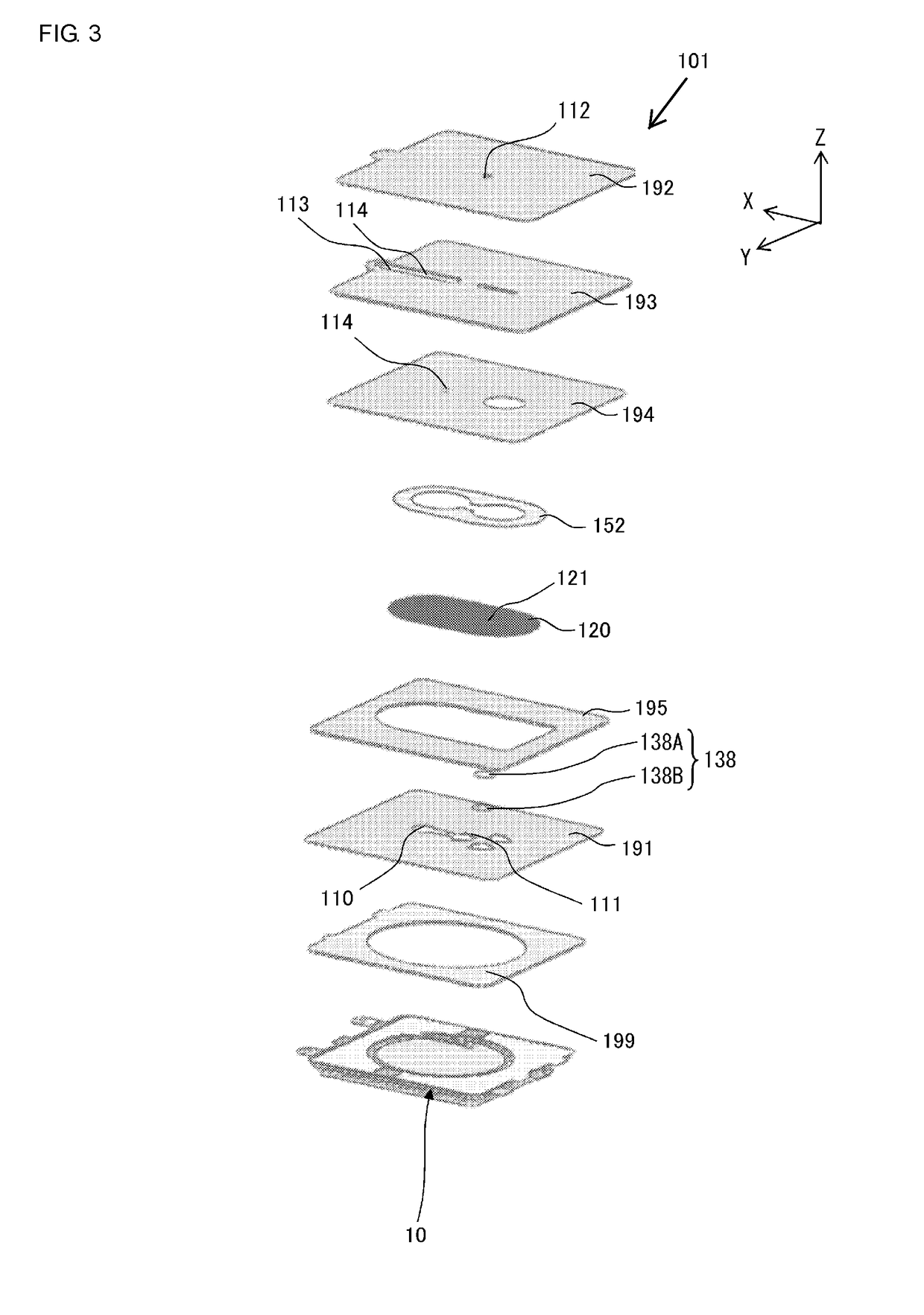
[0036]The valve 101 includes a first plate 191 having first vent holes 110 and 111, a channel forming plate 190 having an exhaust hole 113 and an exhaust channel 114, a second plate 192 having a second vent hole 112, and an edge separation plate 199. The channel forming plate 190 is composed of an intermediate plate 193, an exhaust channel forming plate 194, and a frame plate 195.
[0037]The valve 101 constitutes a check valve 160 and an exhaust valve 170. A manchette rubber tube 109A in the cuff 109 is joined to the periphery of the second vent...
second embodiment
[0099]A gas control device according to the present disclosure is described below.
[0100]FIG. 6 is a cross-sectional view of a main portion of a gas control device 200 according to the second embodiment of the present disclosure. FIG. 7 is an exploded perspective view of a valve 201 illustrated in FIG. 6. The gas control device 200 in the second embodiment differs from the gas control device 100 in the first embodiment in that it includes a channel forming plate 290 including a frame plate 296 and a non-return plate 295. The channel forming plate 290 differs from the channel forming plate 190 in the first embodiment in that it includes a diaphragm 220 and a movable portion 221. A first plate 291 differs from the first plate 191 in shape. The other respects are the same and are not described here.
[0101]The valve 201 constitutes a check valve 260 and an exhaust valve 270. The check valve 260 includes the movable portion 221 and a valve seat 238 positioned around the first vent hole 111...
third embodiment
[0115]Next, a gas control device according to the present disclosure is described.
[0116]FIG. 10A is an enlarged side cross-sectional view that illustrates a peripheral region of an exhaust hole in a valve according to the third embodiment. FIG. 10B is an enlarged plan view that illustrates the peripheral region of the exhaust hole in the valve according to the third embodiment. FIG. 10B is a plan view seen from the side near the first plate, that is, the side near the pump.
[0117]The gas control device according to the third embodiment differs from that according to the first embodiment in the structure of the peripheral region of the exhaust hole in the valve. The other configuration of the gas control device according to the third embodiment is substantially the same as that of the gas control device according to the first embodiment, and the description about similar points is omitted.
[0118]As illustrated in FIGS. 10A and 10B, the exhaust hole 113 is positioned in a first end of t...
PUM
 Abstract
Description
Claims
Application Information