Method of Producing Cuff of Sphygmomanometer Having Automatic Cuff Winding Mechanism

a technology of sphygmomanometer and winding mechanism, which is applied in the direction of metal working apparatus, angiography, metal-working apparatus, etc., can solve the problems of blood pressure information measurement accuracy, wrinkles that affect the measurement accuracy of blood pressure information, and the applied area cannot be evenly pressured, so as to achieve high accuracy the effect of blood pressure measurement of the patien

Active Publication Date: 2012-09-27
OMRON HEALTHCARE CO LTD
View PDF5 Cites 20 Cited by
  • Summary
  • Abstract
  • Description
  • Claims
  • Application Information

AI Technical Summary

Benefits of technology

[0019]An advantage of one or more embodiments of the present invention is that due to the use of cylindrical jig wrinkles are difficult to be created on a surface of the fluid bladder, and as such, the blood pressure of the patient can be measured with high accuracy without causing discomfort to the patient at the time of measuring blood pressure.

Problems solved by technology

When wrinkles occur in the air bladder, the skin gets wound in the occurring wrinkle and causes blood congestion.
The wrinkle adversely affects the measurement accuracy of the blood pressure information when rapid internal pressure fluctuation occurs when the wrinkle disappears or decreases when the air bladder is compressed or decompressed.
Moreover, when deep wrinkles occur in the air bladder, an applied area cannot be evenly pressurized or the wrinkle blocks the flow of air to the inner part of the air bladder and an artery cannot be sufficiently pressurized.
In addition, because the applied area where the cuff is applied has individual differences, the frequency in the occurrence of wrinkles is different due to differences in shape of the applied area (mainly the differences of perimeter, differences of curvature, and the like), and the occurrence of wrinkles can be a cause to variations in measurement accuracy.

Method used


Image

  • Method of Producing Cuff of Sphygmomanometer Having Automatic Cuff Winding Mechanism
  • Method of Producing Cuff of Sphygmomanometer Having Automatic Cuff Winding Mechanism
  • Method of Producing Cuff of Sphygmomanometer Having Automatic Cuff Winding Mechanism

Examples


Embodiment Construction

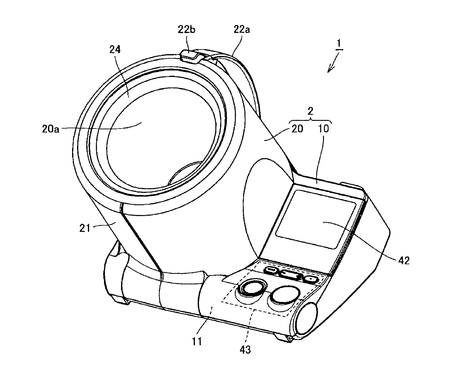
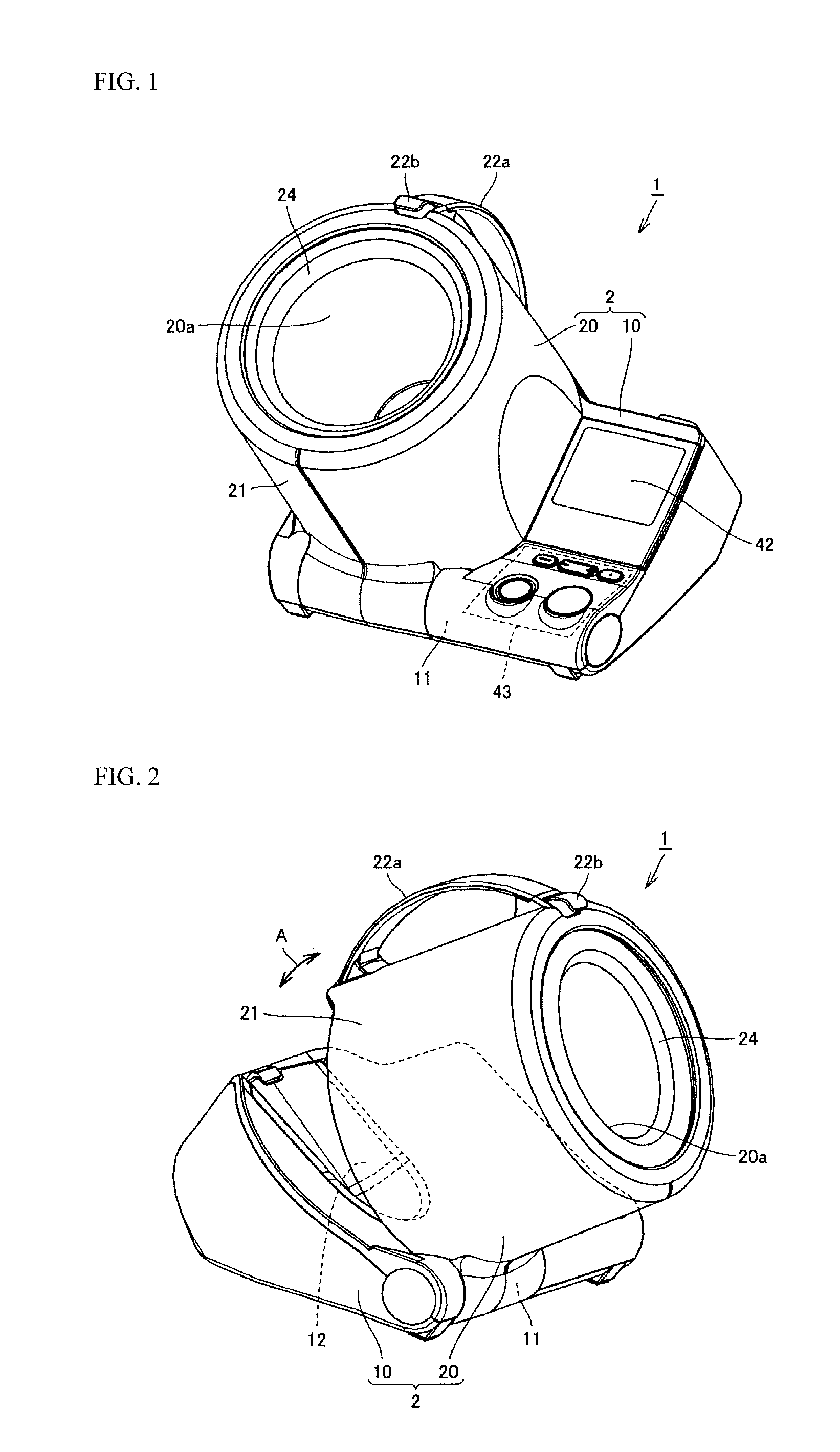
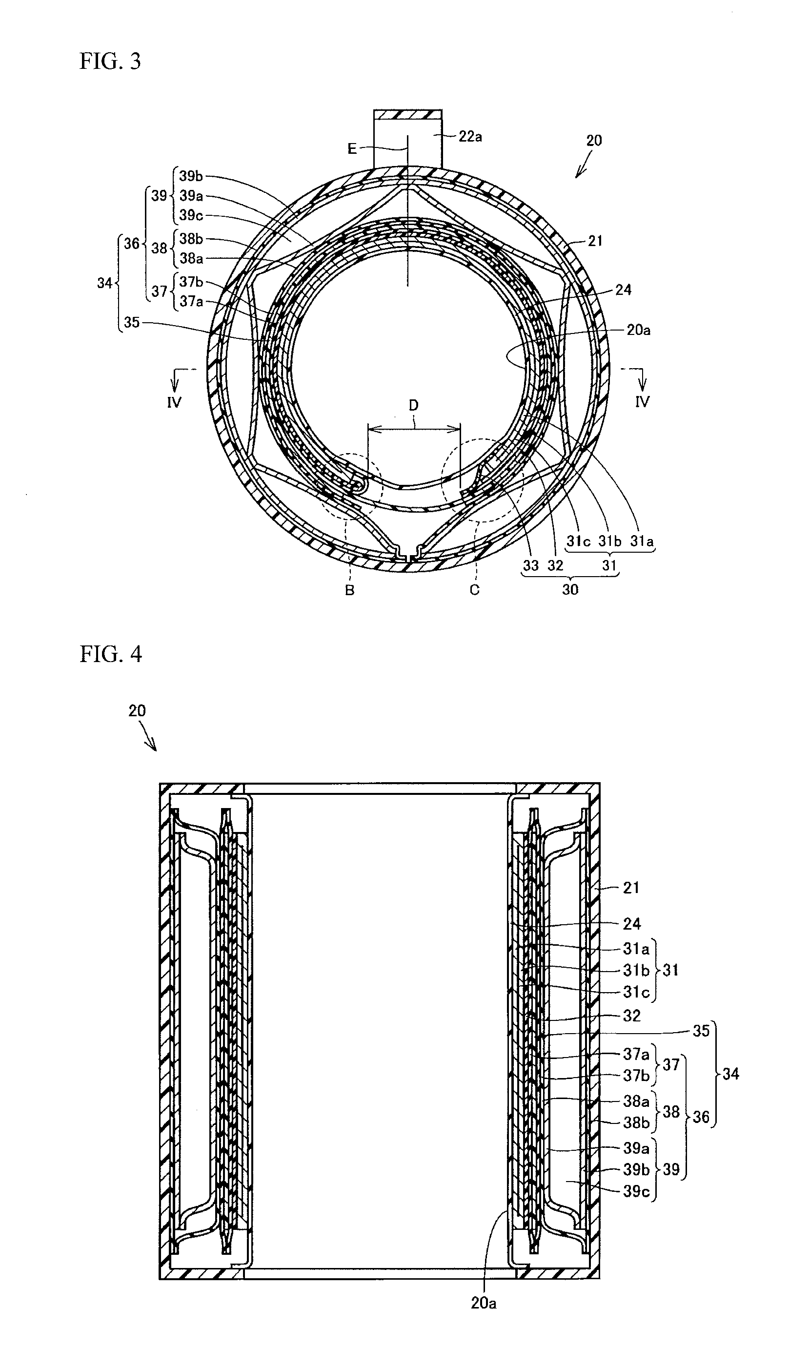
[0038]Hereafter, embodiments of the present invention are explained with reference to drawings. Note that in the embodiments illustrated below, a description is given illustrating an example of a cuff for an upper arm type sphygmomanometer that equips an automatic cuff winding mechanism for the cuff for a blood pressure information monitoring device that is manufactured by one or more embodiments of the present invention

[0039]FIGS. 1 and 2 are schematic perspective views illustrating a sphygmomanometer having a cuff that is manufactured according to the method of an embodiment of the invention FIG. 1 is a drawing when viewing the sphygmomanometer from the front right oblique upward direction. FIG. 2 is a figure when the sphygmomanometer is viewed from front left oblique upward direction. Note that FIG. 1 illustrates the sphygmomanometer in a state of non-use, and FIG. 2 illustrates the state after an upper arm insertion part is rotated to the position where the upper arm can be inse...


PUM

PropertyMeasurementUnit
perimeteraaaaaaaaaa
diameteraaaaaaaaaa
outer diameteraaaaaaaaaa

Abstract

In a method of producing a cuff of a sphygmomanometer having an automatic cuff winding mechanism, the cuff includes a band-shaped fluid bladder forming a cavity for inserting a user's arm therein, a shape maintenance member wound on the band-shaped fluid bladder, a band-shaped bag wound on the shape maintenance member, and a cylindrical elastic plate housed in the band-shaped bag. The method includes winding the band-shaped fluid bladder on an outer circumferential surface of a cylindrical jig having approximately the same outer diameter as the cavity of the band-shaped fluid bladder, winding the shape maintenance member on an outer circumferential surface of the band-shaped fluid bladder, winding the band-shaped bag on an outer circumferential surface of the shape maintenance member, removing the cylindrical jig from the band-shaped fluid bladder, and housing the cylindrical elastic plate inside the band-shaped bag.

Description

BACKGROUND OF INVENTION[0001]The present invention relates to a method of producing a cuff of a sphygmomanometer having an automatic cuff winding mechanism.[0002]In order to understand the health condition of a patient, it is very important to measure blood pressure information. In recent years, efforts to detect cardiac load or arterial sclerosis have been made by measuring pulse wave, systolic blood pressure, and diastolic blood pressure, the effectiveness of which is widely known as a major indicator to analyze the risks of cardiovascular diseases such as cerebral embolism, cardiac arrest, and cardiac infarction.[0003]A blood pressure information monitoring device is a device to measure these types of blood pressure information and is expected to be further used in the field of early diagnosis, prevention, and treatment. Moreover, blood pressure information includes various kinds of cardiovascular type of information such as various kinds of indicators that indicate systolic bloo...

Claims


Application Information

Patent Timeline
Patent Type & Authority Applications(United States)
IPC IPC(8): B23P11/00
CPCY10T29/49826A61B5/02233Y10T29/49877Y10T29/49879
Inventor ASHIDA, TAMEO
Owner OMRON HEALTHCARE CO LTD
Why Eureka
Try Eureka