Hemostatic device

a technology of hemostasis and hematoma, which is applied in the field of hemostasis devices, can solve the problems of numbness or pain, occluded blood vessels, etc., and achieve the effects of reducing pain, preventing blood leakage, and preventing bleeding

Active Publication Date: 2018-02-15
TERUMO KK
View PDF0 Cites 25 Cited by
  • Summary
  • Abstract
  • Description
  • Claims
  • Application Information

AI Technical Summary

Benefits of technology

[0008]According to the hemostatic device of the disclosure herein, when the inflation portion inflates, the inflation portion includes the plurality of convex portions which are aligned with each other in the width direction of the band. Therefore, when the band is wrapped around the limb, the convex portions of the inflation portion are disposed so as to be aligned with each other in an extending direction of a hemostasis-requiring blood vessel. Therefore, the hemostatic device according to the disclosure can cause the convex portions to apply a dispersed compressive force to a plurality of locations on the blood vessel, when the inflation portion inflates. That is, the hemostatic device according to the disclosure can cause the inflation portion to apply the dispersed compressive force to the plurality of locations in the blood vessel. Accordingly, the hemostatic device can perform hemostasis while suppressing pain occurrence as much as possible.
[0009]The hemostatic device may include a marker for aligning the inflation portion with the hemostasis-requiring site. In this manner, the hemostatic device causes the marker to align with a puncture site, thereby enabling the inflation portion to compress a desired position on a body surface. Therefore, the hemostatic device according to the disclosure herein can restrain blood leakage caused by misalignment of the inflation portion, and can reliably perform the hemostasis at the puncture site.
[0010]The marker may be disposed between the adjacent convex portions. In this manner, the hemostatic device causes the marker to align with the puncture site, thereby enabling the puncture site to be pinched between two convex portions when the inflation portion inflates. Hence, the hemostatic device according to the disclosure herein can compress the puncture site by pinching both an upstream side and a downstream side of the puncture site of the blood vessel. Accordingly, the hemostatic device can restrain the convex portions from excessively compressing the puncture site. In this manner, the hemostatic device can achieve an excellent hemostatic effect while relieving pain. Note that, in a case of an artery, the upstream side of the blood vessel means a direction closer to the heart of the blood vessel. In addition, the downstream side of the blood vessel means a direction away from the heart of the blood vessel.
[0011]The marker may be eccentrically disposed on one side in the width direction of the band. In this manner, the hemostatic device causes the marker to align with the puncture site. Accordingly, when the inflation portion is disposed at the puncture site, it becomes easy to set the compressive force applied to the upstream side of the blood vessel to be stronger than that applied to the downstream side of the blood vessel. Therefore, the compressive force applied to the upstream side of the blood vessel, which is closer to the heart and has a higher blood pressure, can be stronger than the compressive force applied to the downstream side of the blood vessel. Accordingly, it is possible to achieve an excellent hemostatic effect while the stress or burden on a living body is reduced as much as possible without excessively inhibiting a blood flow.
[0012]The hemostatic device may have a curved plate formed of a material harder than that of the band, and the band may be configured to hold the curved plate so as to overlap the inflation portion. In this manner, if the hemostatic device causes the inflation portion to inflate after a user wears the hemostatic device, the curved plate restrains the inflation portion from inflating in a direction away from the body surface of the limb, and thus, the compressive force of the inflation portion concentrates on the hemostasis-requiring blood vessel. Therefore, the hemostatic effect is improved, and it is possible to avoid a possibility of compressing other blood vessels or nerves which do not require the hemostasis. Accordingly, it is possible to inhibit the occurrence of hand numbness or poor blood circulation. In addition, since the curved plate is curved, the compressive force of the inflation portion can be effectively received by the curved plate. Accordingly, an excellent hemostatic effect can be achieved by effectively adjusting the compressive force applied to the limb.
[0013]The hemostatic device may also have a pressing member that presses the inflation portion between the curved plate and the inflation portion, and the pressing member may be disposed so as to overlap the inflation portion. In this manner, a hemostatic member can cause the pressing member to adjust a direction in which the inflation portion applies pressure to the puncture site. Therefore, a hemostatic effect is improved, and it is possible to avoid a possibility of compressing other blood vessels or nerves which do not require the hemostasis. Accordingly, it is possible to inhibit the occurrence of hand numbness or poor blood circulation.

Problems solved by technology

Consequently, in some cases, numbness or pain may be caused, or the blood vessel may be occluded.

Method used


Image

  • Hemostatic device
  • Hemostatic device
  • Hemostatic device

Examples


Embodiment Construction

[0029]Hereinafter, an exemplary embodiment according to the disclosure herein will be described with reference to the drawings. Note that, dimensional proportions in the drawings may be exaggerated and different from actual proportions for convenience of description in some cases.

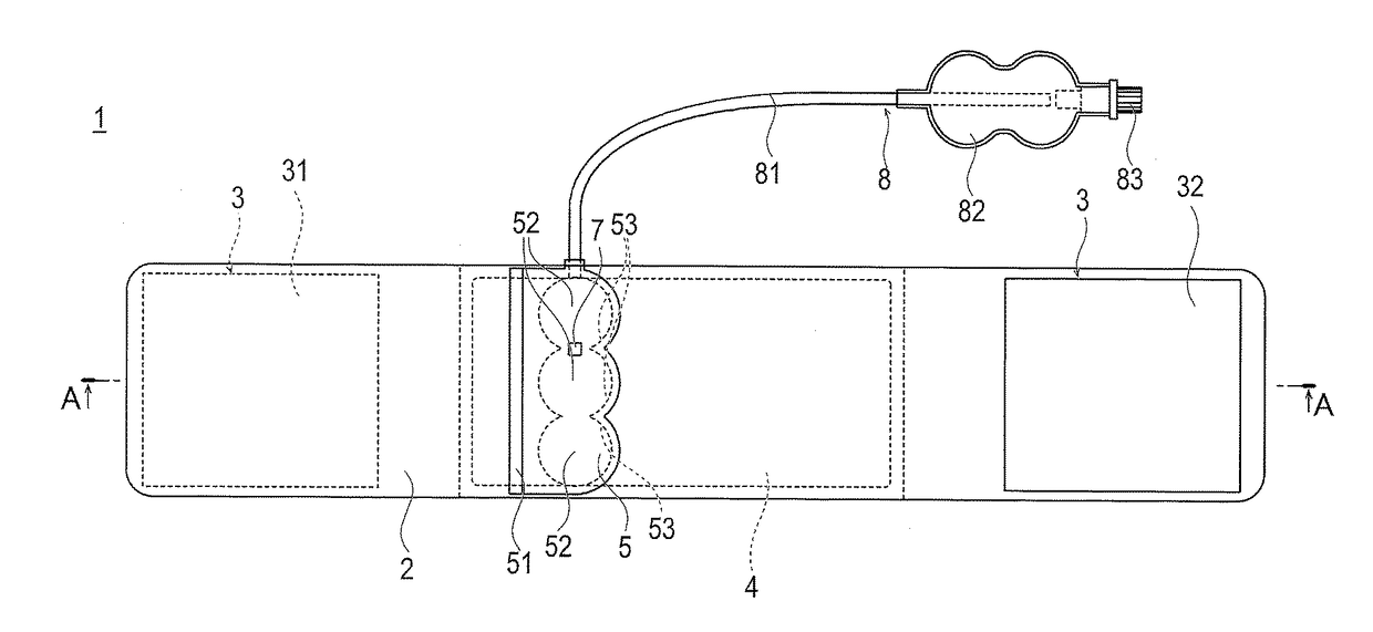
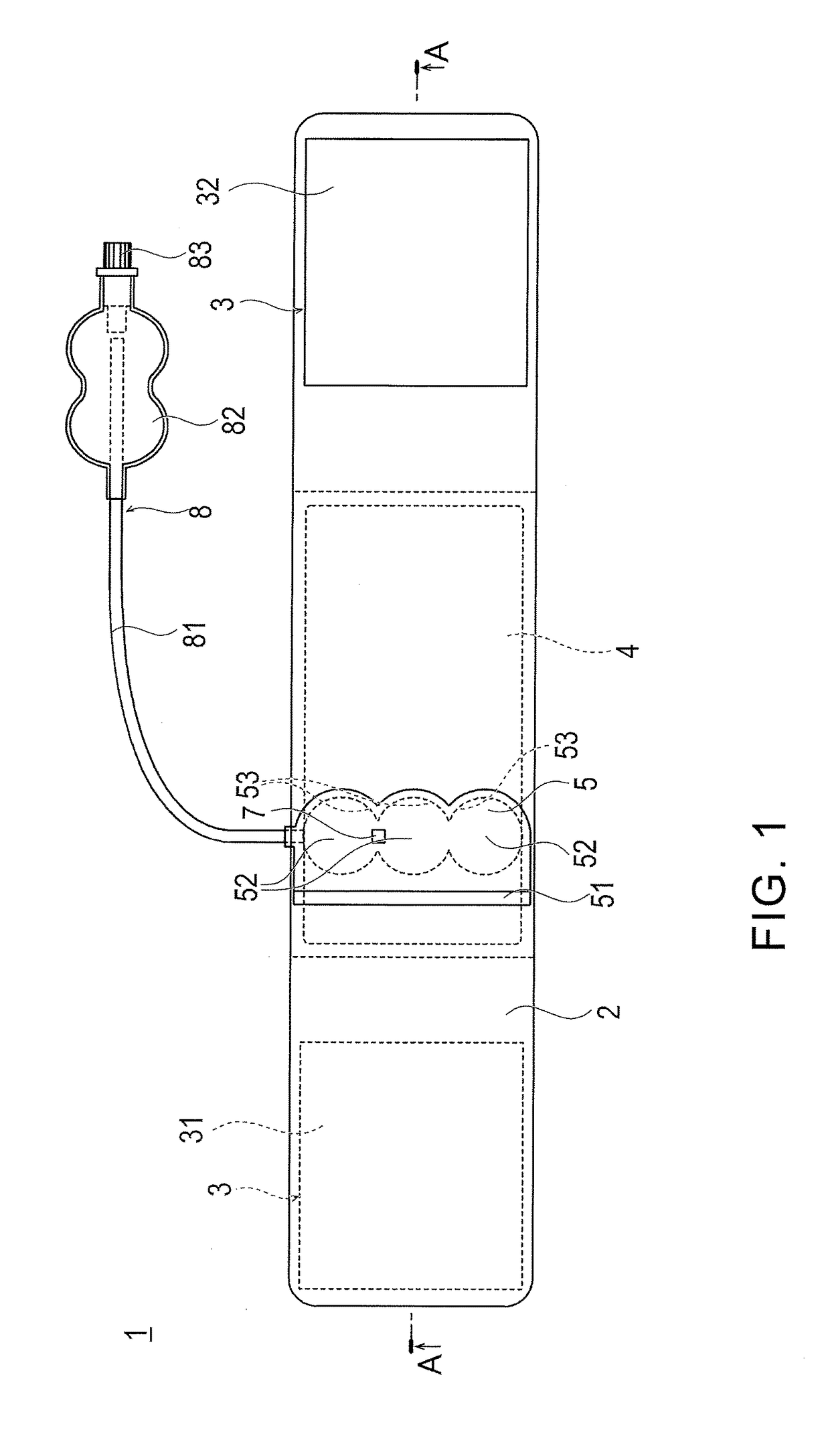
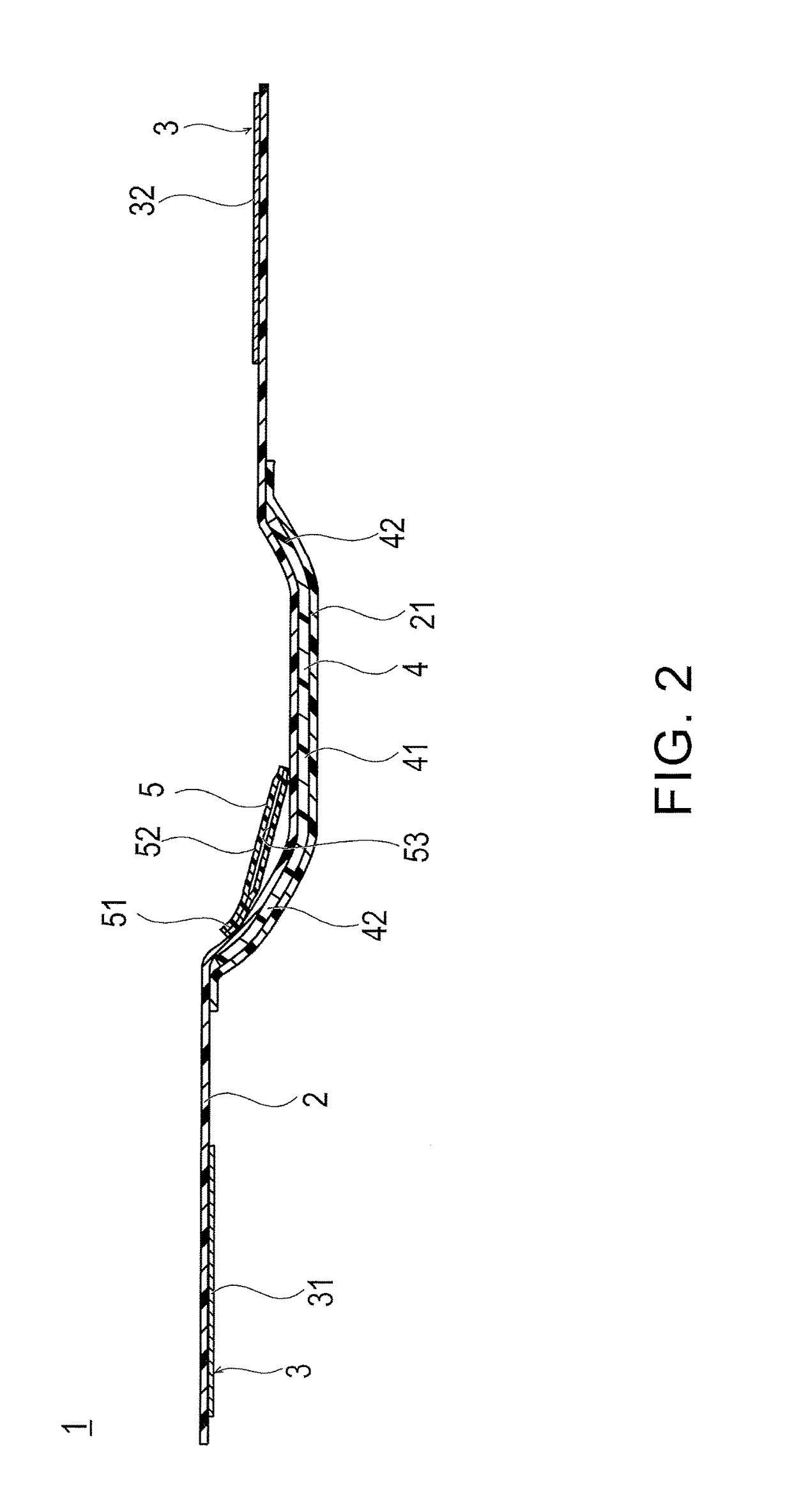
[0030]A hemostatic device 1 according to an exemplary embodiment of the disclosure is used as follows. As illustrated in FIGS. 3 and 4, in order to insert a catheter for treatment and inspection into a blood vessel, an introducer sheath is caused to indwell a puncture site 220 (hemostasis-requiring site) formed in a radial artery 210 of a wrist 200 (limb), and is removed therefrom. Thereafter, the hemostatic device 1 is used for performing hemostasis at the puncture site 220. As illustrated in FIGS. 1 and 2, the hemostatic device 1 includes a band 2 for being wrapped around the wrist 200, a surface fastener 3 (securing portion) that secures the band 2 in a state where the band 2 is wrapped around the wrist ...


PUM


Abstract

A hemostatic device has a flexible band that can be wrapped around a hemostasis-requiring site of a limb, a securing portion that secures the band in a state where the band is wrapped around the limb, and an inflation portion that interlocks with the band, and that inflates when a fluid is injected. The inflation portion has a plurality of convex portions in a width direction orthogonal to a longitudinal direction of the band when the inflation portion inflates.

Description

CROSS-REFERENCE TO RELATED APPLICATIONS[0001]This application is a continuation of International Application No. PCT / JP2016 / 060984 filed on Apr. 4, 2016, which claims priority to Japanese application number 2015-078481 filed on Apr. 7, 2015, the entire contents of which are incorporated herein by reference.TECHNICAL FIELD[0002]The present invention relates to a hemostatic device for performing hemostasis by compressing a punctured site.BACKGROUND ART[0003]In recent years, treatment and inspection have been percutaneously performed by introducing an introducer sheath into a punctured site of a blood vessel in an arm or a leg and inserting a catheter into a lesion area of the blood vessel via a lumen of the introducer sheath. In a case where this method is employed, it is necessary to perform hemostasis at the puncture site after the introducer sheath is removed. In order to perform the hemostasis, a known hemostatic device is used, which includes a band for being wrapped around the p...

Claims


Application Information

Patent Timeline
Patent Type & Authority Applications(United States)
IPC IPC(8): A61B17/135
CPCA61B17/135A61B17/1322A61B17/1325A61B2017/00455A61B2017/00907
Inventor KIMURA, AYAKOHAYASHI, TEPPEI
Owner TERUMO KK
Why Eureka
Try Eureka