Plasma display panel and producing method thereof

A technology for plasma display panels and display electrodes, which is applied to alternating current plasma display panels, tube structural parts, discharge tubes, etc., and can solve problems such as luminance reduction

Inactive Publication Date: 2004-01-21
PANASONIC CORP
View PDF1 Cites 2 Cited by
  • Summary
  • Abstract
  • Description
  • Claims
  • Application Information

AI Technical Summary

Problems solved by technology

Furthermore, since the light-emitting area of ​​the plasma display panel is continuously reduced along with the high-definition, the reduction of luminance will become a worrying problem.

Method used


Image

  • Plasma display panel and producing method thereof
  • Plasma display panel and producing method thereof
  • Plasma display panel and producing method thereof

Examples


Embodiment Construction

[0016] Hereinafter, a plasma display panel according to an embodiment of the present invention will be described with reference to the drawings.

[0017] Embodiment 1

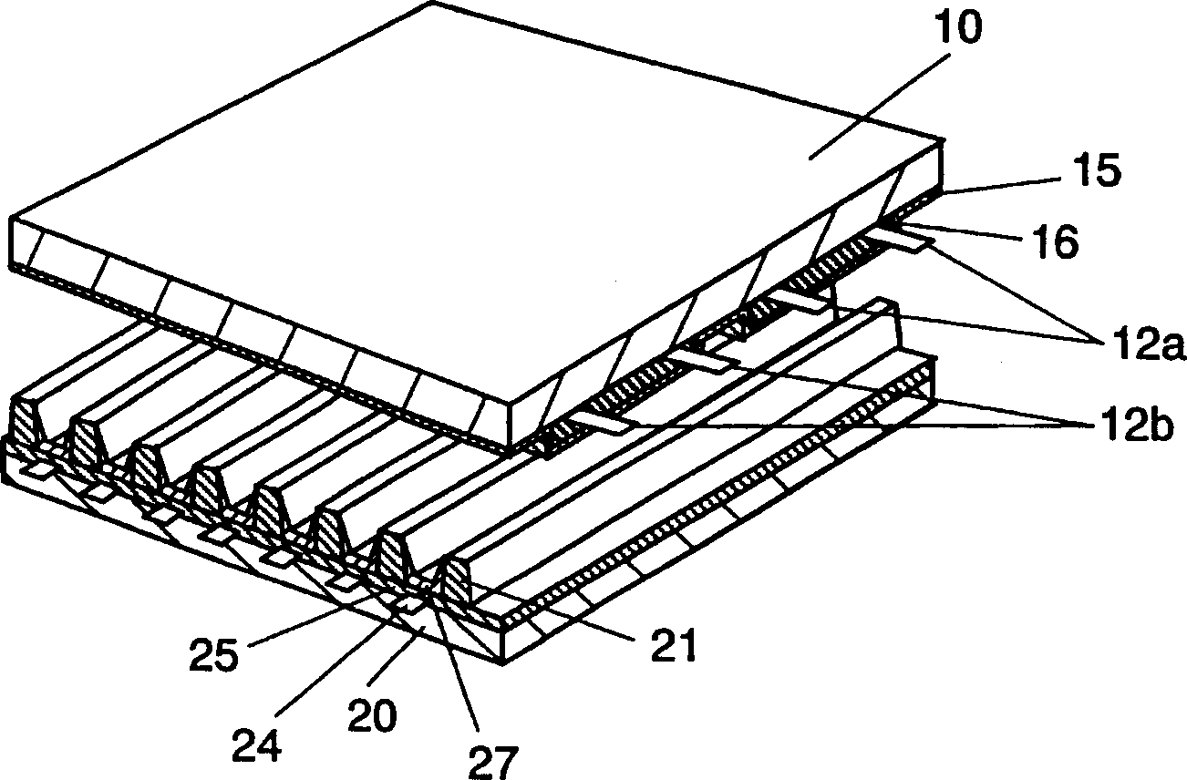
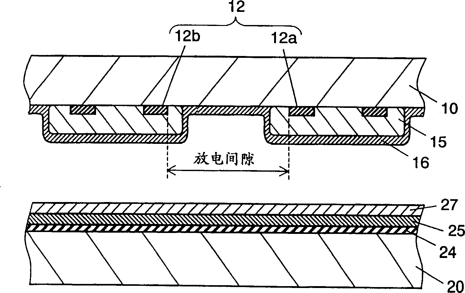
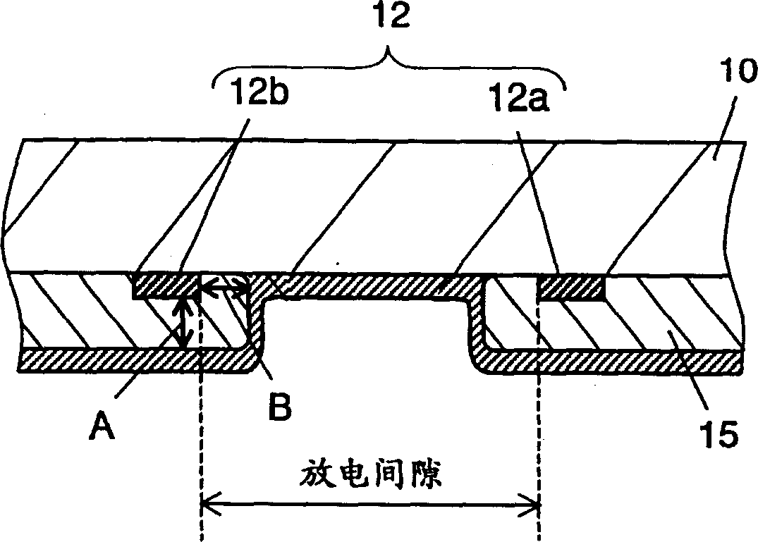
[0018] figure 1 is an exploded perspective view showing the structure of the plasma display panel according to Embodiment 1 of the present invention, figure 2 It is a sectional view showing the structure of the plasma display panel according to Embodiment 1 of the present invention.

[0019] On the front substrate 10, a display electrode pair 12 composed of two display electrode pairs 12a and 12b parallel to each other is provided, and a discharge gap for performing display light emission is formed. The display electrode pairs 12a, 12b are covered with a dielectric layer 15, respectively. However, the dielectric layer 15 is not formed on the discharge gap formed between the display electrode pair 12a, 12b. The protective film 16 is formed so as to cover the dielectric layer 15 and the discharge gap. Ther...


PUM


Abstract

An AC type plasma display panel includes a plurality of pairs of display electrodes 12a and 12b, dielectric layer 15, a data electrode and float electrode 41. A pair of the plurality of pairs of display electrodes 12a and 12b are disposed parallel to each other on front substrate 10 and form a discharge gap for emitting light for display. Dielectric layer 15 is formed on front substrate 10 and covers the plurality of pairs of display electrodes 12a and 12b excluding at least a part of the discharge gap. The data electrode is disposed on a rear substrate, which is placed facing the front substrate across discharge space, in a manner to cross under the display electrodes. Float electrode 41 is disposed at the discharge gap on front substrate 10.

Description

technical field [0001] The invention relates to a plasma display panel capable of high-brightness and high-efficiency picture display. Background technique [0002] The plasma display panel is a visually excellent display characterized by a large screen, thin shape, and light weight. Plasma display panels are roughly divided into AC type and DC type. In addition, as the discharge form, there are surface discharge type and opposite discharge type, but they are suitable for high definition, and from the perspective of ease of manufacture, surface discharge AC type plasma display Boards are now in the mainstream. [0003] However, the luminance and luminous efficiency of plasma display panels are still low at present, and as a display device, the luminous efficiency is only about 1 / 3 compared with that of a general CRT. Therefore, various plasma display panels are being developed for the purpose of increasing efficiency. [0004] It is known that the luminous efficiency of a...

Claims


Application Information

Patent Timeline
Patent Type & Authority Applications(China)
IPC IPC(8): H01J17/49
CPCH01J2211/326H01J11/30H01J11/38H01J11/12
Inventor 结城治宏本间义康
Owner PANASONIC CORP
Why Eureka
Try Eureka