Distribution board

A technology of switchboards and conductive rods, applied in electrical components, substation/switch layout details, etc., can solve problems such as troublesome work

Inactive Publication Date: 2004-02-18
MATSUSHITA ELECTRIC WORKS LTD
View PDF2 Cites 7 Cited by
  • Summary
  • Abstract
  • Description
  • Claims
  • Application Information

AI Technical Summary

Problems solved by technology

However, it is difficult to judge the extent to which the conductive rod 100' and the insulating cover should be cut off, so it is very troublesome to change from a 1P type branch circuit breaker to a 2P type branch circuit breaker

Method used


Image

  • Distribution board
  • Distribution board
  • Distribution board

Examples


Embodiment Construction

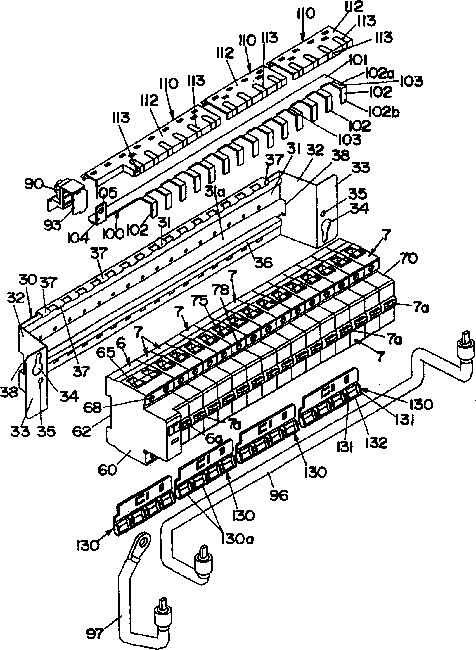
[0029] Below, see Figure 1 to Figure 14 , to illustrate the switchboard of this embodiment.

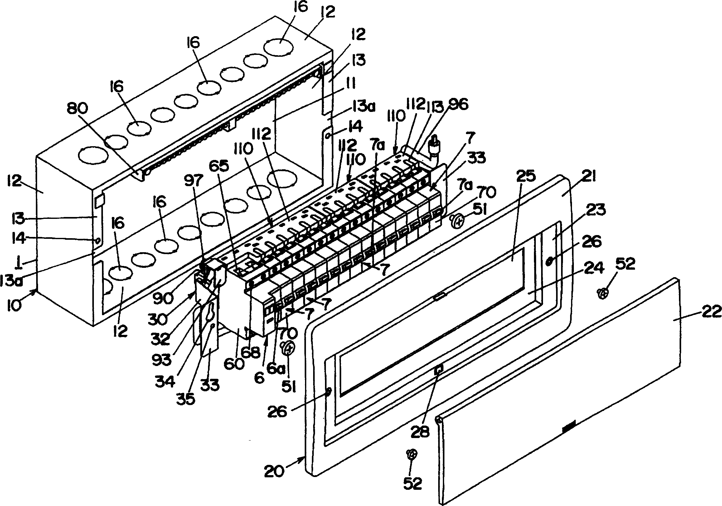
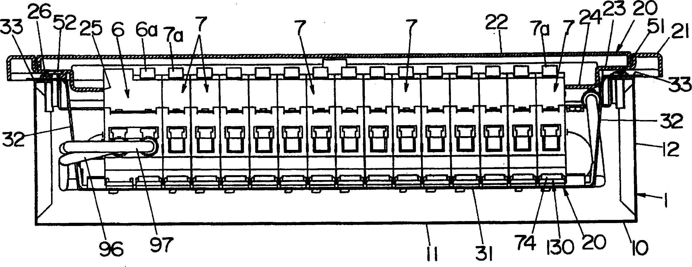
[0030] Make the switchboard of this embodiment, as figure 2 As shown in FIG. 4 , a main circuit breaker 6 and a plurality of branch circuit breakers 7 are arranged in the box body 1 as internal bodies. The main circuit breaker 6 and the plurality of branch circuit breakers 7 are arranged in a row in the short side direction. The box body 1 is composed of a box body 10 made of metal with an open front, and a cover body 20 joined to the box body 10 so as to close the opening of the box body 10 . In addition, the box body 10 is embedded in a wall surface such as a wall.

[0031] The box body 10 is composed of a rectangular rear panel 11 and side panels 12 provided forward from the periphery of the rear panel 11 . From the front edges of the left and right side plates 12 , supporting pieces 13 , 13 are extended in a direction approaching each other, and screw holes 14 , 14 are forme...


PUM


Abstract

A distribution board where the changing work from an 1P type branch breaker to a 2P type branch breaker becomes easier. A conductive bar (100) connected via a transmission line (97) on power side to the output terminal on power side of a master breaker (6) is connected to the input terminal of a branch breaker (7). The conductive bar (100) has a strip-shaped bar body (101), and branch connecting pieces (102) are a plurality of branch connection parts extended from one side edge in widthwise direction of the bar body (101). An insulating cover (110) covers the exposed section of the branch connecting piece (102) in condition that the conductive bar (100) is connected to each branch breaker (7), and is attached to the bar body (101) of the conductive bar (100). At a section where the branch connecting piece (102) and the bar body (101) are connected with each other, a cutting groove (103) of a cutting auxiliary part is made, and at the insulating cover (110), a cut groove (113) extends to roughly the same position as the cutting groove (103) along the branch connecting piece (102).

Description

technical field [0001] The invention relates to a switchboard equipped with DIN standard circuit breakers. Background technique [0002] Such a switchboard has been described in JP-A-2001-28810. The switchboards mentioned in the bulletin, such as Figure 15 ~ Figure 17 As shown, in the box body 10, a so-called DIN rail 40 for mounting an internal body is disposed. The cross-sectional shape of the DIN rail 40 is U-shaped, and protruding pieces 41 , 41 are extended from the front edges of the two leg pieces in a direction away from each other. Correspondingly, the branch circuit breaker 7 to be installed on the DIN guide rail 40 is formed with a local embedding groove 72 capable of embedding the DIN guide rail 40 at the back of its body, and on the inner side of one of the embedding grooves 72 is formed a The stop slot 73 that can stop the protruding piece 41 on one side of the DIN guide rail 40 from moving is provided on the other inner side of the insertion groove 72, whic...

Claims


Application Information

Patent Timeline
Patent Type & Authority Applications(China)
IPC IPC(8): H02B1/40H02B1/42
Inventor 矢野刚金平芳三
Owner MATSUSHITA ELECTRIC WORKS LTD
Why Eureka
Try Eureka