
Battery outer case for receiving a flat battery pack joined by seam-rolling

a battery pack and outer case technology, applied in the field of battery outer cases, can solve the problems of reducing electrical insulation, reducing the electrical insulation of the battery pack, and affecting the electrical insulation of the outer case,

Active Publication Date: 2011-03-22
ENVISION AESC JAPAN LTD +1
View PDF12 Cites 4 Cited by
  • Summary
  • Abstract
  • Description
  • Claims
  • Application Information

AI Technical Summary

Benefits of technology

The present invention provides a battery outer case for a flat battery pack that reduces the length of protrusion of joint points between the metal container main body and the metal lid, achieving space saving. The battery outer case is made of a metal container main body and a metal lid that are sealed together to create an air-permeable space. The flat battery pack is smoothly received in the metal container main body and the seam joint between the metal container main body and the metal lid is carried out by seaming, reducing the risk of thermal damage or deformation. The battery outer case is also suitable for laminate type batteries and can provide electrical insulation against exposed tabs of the thin batteries.

Problems solved by technology

In the jointing or coupling techniques as shown in FIG. 4A and FIG. 4B, however, there is the following problem.
In such a case of abutment joint or connection, however, spatter generated upon welding can be easily dispersed into the inside of the container, and heat can also be transmitted to the inside of the container, so the flat battery pack 101 is liable to be damaged.
In particular, in the case of a thin battery with its exterior being formed of a laminate film, the laminate layer can be damaged to induce a reduction in electrical insulation.
In this case, however, there arises another problem.
In the case of such a caulking structure, however, the gasket 202 is needed as an additional part, resulting in an increase in the number of required parts.

Method used


Image

  • Battery outer case for receiving a flat battery pack joined by seam-rolling
  • Battery outer case for receiving a flat battery pack joined by seam-rolling
  • Battery outer case for receiving a flat battery pack joined by seam-rolling

Examples


Embodiment Construction

[0043]Now, the preferred embodiments of the present invention will be described below while referring to the accompanying drawings.

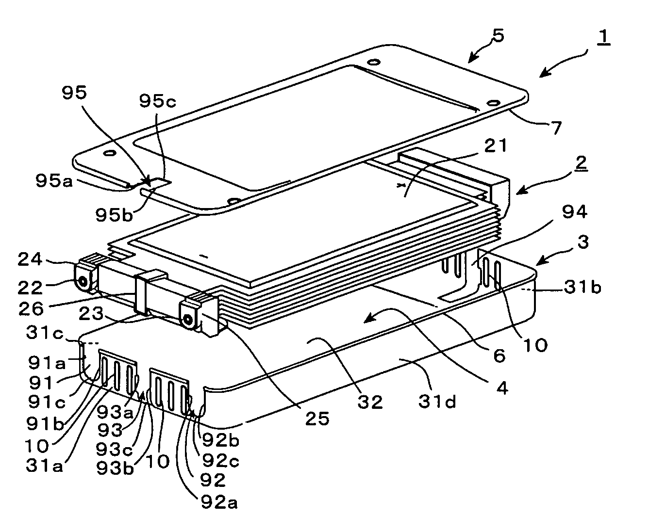
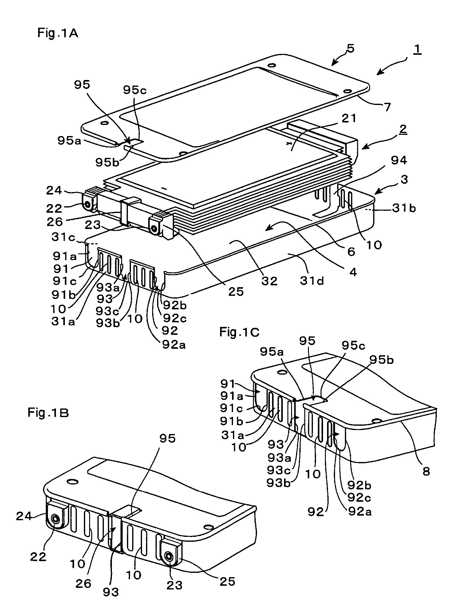
[0044]FIG. 1 shows a battery outer case according to one embodiment of the present invention.

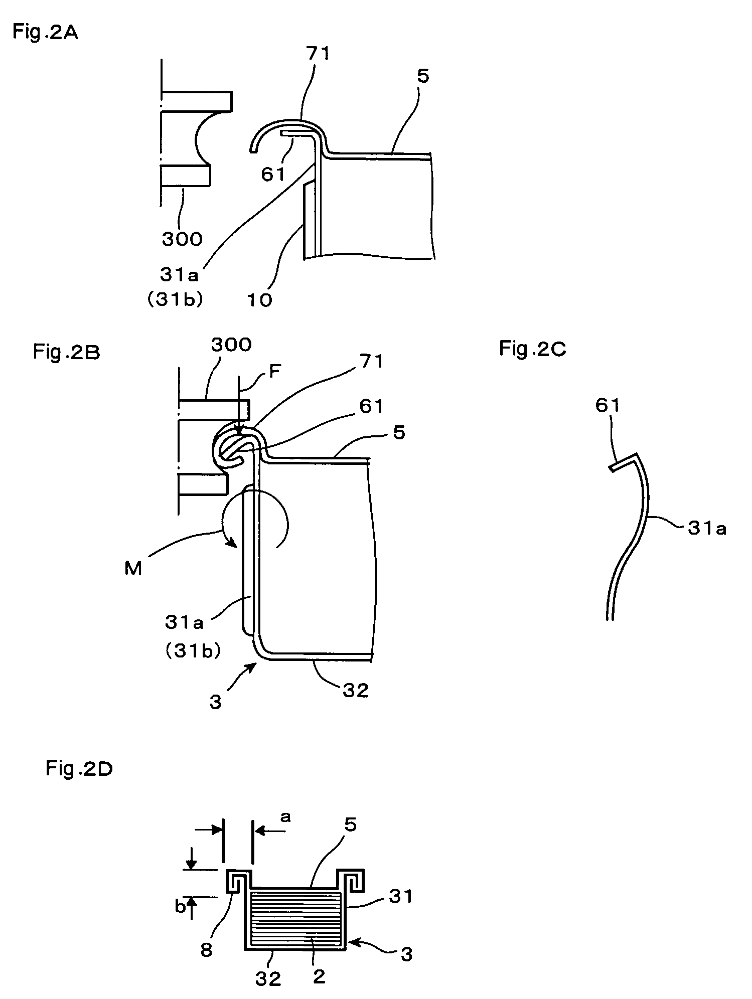
[0045]The battery outer case, generally designated at 1, includes a metal container main body 3 with an open upper surface and having a flat battery pack 2 housed or received therein, and a metal lid 5 that serves to close an opening 4 formed in the metal container main body 3, an open end periphery 6 of the metal container main body 3 and a lid end periphery 7 of the metal lid 5 being joined to each other by seaming. To this end, seam portions 8 are formed at the joint portions of the open end periphery 6 of the metal container main body 3 and the lid end periphery 7, respectively.

[0046]The flat battery pack 2 is constructed as follows. That is, inside a battery exterior composed of a laminate film there are laminated or stacked a plurality of serially connected...


PUM

PropertyMeasurementUnit
widthsaaaaaaaaaa
thicknessaaaaaaaaaa
thicknessaaaaaaaaaa

Abstract

A battery outer case can provide space saving by reducing the length of protrusion of joint portions between a metal container main body and a metal lid, is free from a thermal influence, and can make it unnecessary to employ additional or extra parts such as a gasket. The battery outer case includes the metal container main body having at least one surface opened with a flat battery pack composed of flat type batteries received therein, and a metal lid for closing an opening formed in the metal container main body. The inside of the container is in communication with the outside thereof so as to have air permeability, and an open end periphery of the metal container main body and a lid end periphery of the metal lid are joined to each other by seaming.

Description

[0001]This application claims the benefit of Japanese Application No. 2004-276250, filed Sep. 22, 2004, the entirety of which is incorporated herein by reference.BACKGROUND OF THE INVENTION[0002]1. Field of the Invention[0003]The present invention relates to a battery outer case that houses a flat battery pack such as, for example, a laminate cell battery, etc., composed of a plurality of thin batteries laminated one over another.[0004]2. Description of the Related Art[0005]As a battery outer case in which this kind of flat battery pack is housed, there can be considered such a one as shown in FIGS. 4A through 4F.[0006]Specifically, a battery outer case 100 shown in FIG. 4A includes a metal container main body 102 in which a flat battery pack 101 is housed therein, and a metal lid 103 that serves to close an opening formed in the metal container main body 102. An outwardly protruding connection flange 104 is formed at an open end of the metal container main body 102, and a connectio...

Claims


Application Information

Patent Timeline
Patent Type & Authority Patents(United States)
IPC IPC(8): H01M2/04H01M2/02
CPCH01M2/0285H01M2/0404H01M10/0436Y10T29/49108Y10T29/4911Y02E60/10H01M50/20H01M50/10H01M10/049
Inventor AMAGAI, RYUICHIOOGAMI, ETSUOYAJIMA, SEIJIROUSEGAWA, TERUOTSUKADA, KAZUHIKO
Owner ENVISION AESC JAPAN LTD
Learn More