Airbag device

a technology of airbags and retainers, which is applied in the direction of pedestrian/occupant safety arrangements, vehicular safety arrangements, vehicle components, etc., can solve the problems of difficult practical use of retainers and difficulty in reducing the weight of airbag devices, so as to prevent the protrusion of airbags, prevent the generation of abnormal noise, and easy to engag

Inactive Publication Date: 2014-11-25
JOYSON SAFETY SYST JAPAN KK
View PDF29 Cites 2 Cited by
  • Summary
  • Abstract
  • Description
  • Claims
  • Application Information

AI Technical Summary

Benefits of technology

[0020]Furthermore, in addition to the engagement member disposed in the longitudinal direction, the second engagement member is disposed in the short direction. In this manner, the four side surfaces of the retainer can be engaged with the inner case and, thus, protrusion of the airbag can be effectively prevented.
[0021]Furthermore, by forming the engagement member as one of a hook and a holding belt, the retainer can be easily engaged with the inner case. In particular, when the holding belt is employed as the engagement member, the holding belt can be disposed between the retainer and the inner case and, thus, generation of abnormal noise can be prevented.
[0022]Still furthermore, by forming the holding belt serving as the engagement member from belt-like fabric, such as webbing, the weight of the retainer can be reduced. In addition, the retainer can be prevented from coming off.
[0023]Yet still furthermore, by using a rivet as fixing means of the holding belt and the retainer, the holding belt can be easily fixed from the outer side of the retainer.
[0024]Yet still furthermore, by fixing the holding belt to the raised portion of the retainer, the length of protrusion of the fixing member toward the inside of the retainer can be reduced and, thus, the inner space of the retainer can be effectively used. In addition, by forming a notch in the airbag cover, the fixing member does not interfere with the retainer when the retainer is fixed to the airbag cover. Accordingly, even when the raised portion is formed, a sufficient capacity of the inner space of the retainer can be obtained.
[0025]Yet still furthermore, by forming a resin retainer, the weight of the retainer can be reduced and can be easily molded. In addition, by separating the inflator fixing attachment hole and the bracket fixing attachment hole from each other and using the back plate that covers the two holes, the bottom surface portion of the retainer can be sandwiched. Accordingly, even when the retainer is made of resin, the inflator and the bracket can be easily fixed to the retainer.

Problems solved by technology

However, such a solution to the fish mouth phenomenon problem increases the weight of the retainer and, thus, it is difficult to reduce the weight of the airbag device, which is problematic.
However, the strength of such a retainer is insufficient to solve the fish mouth phenomenon problem and, thus, practical use of the retainer is difficult, which is problematic.

Method used


Image

  • Airbag device
  • Airbag device
  • Airbag device

Examples


first embodiment

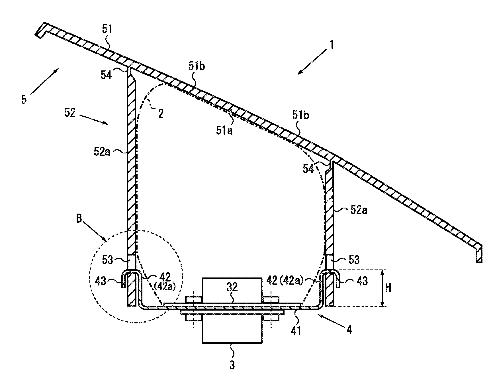
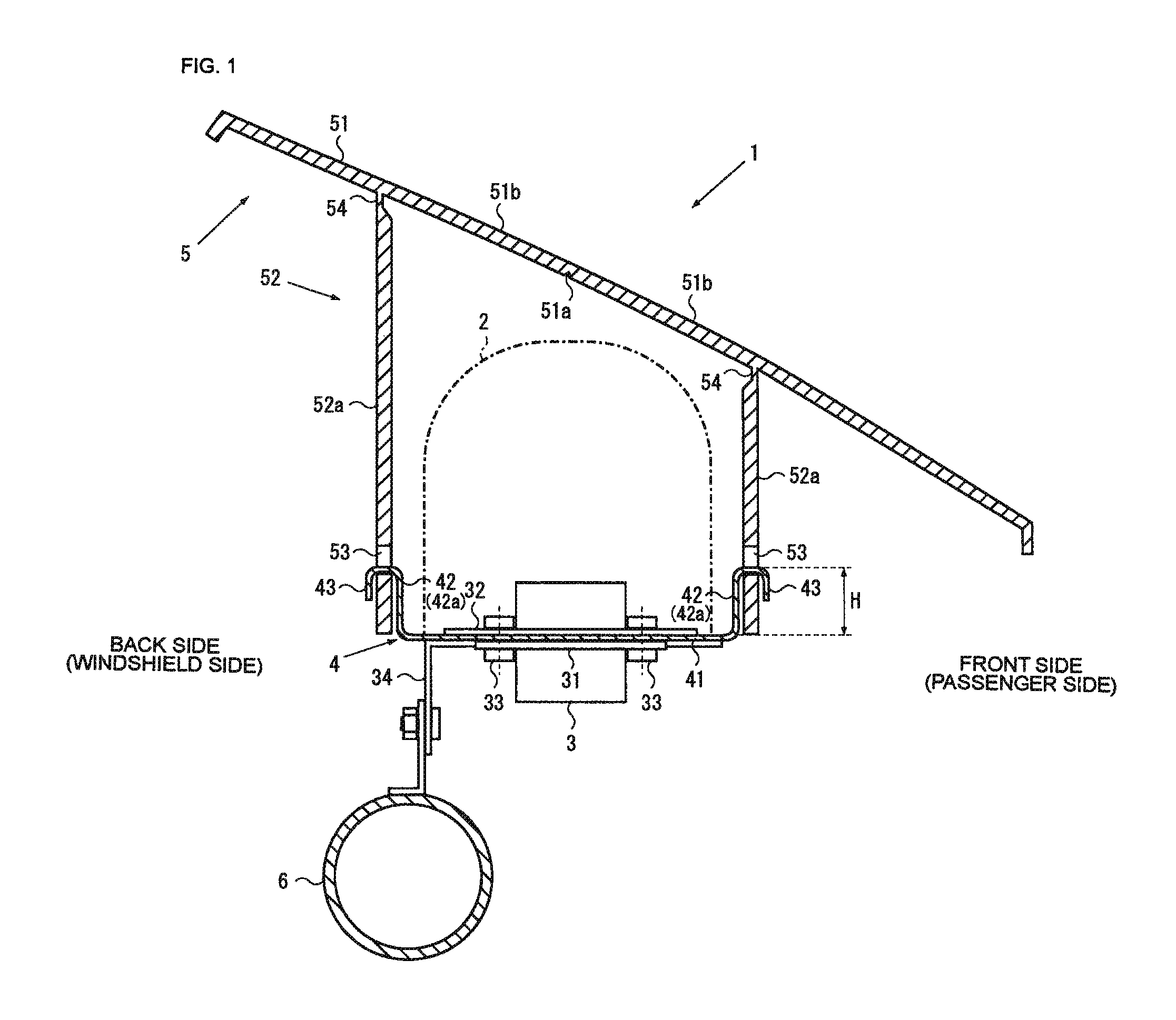
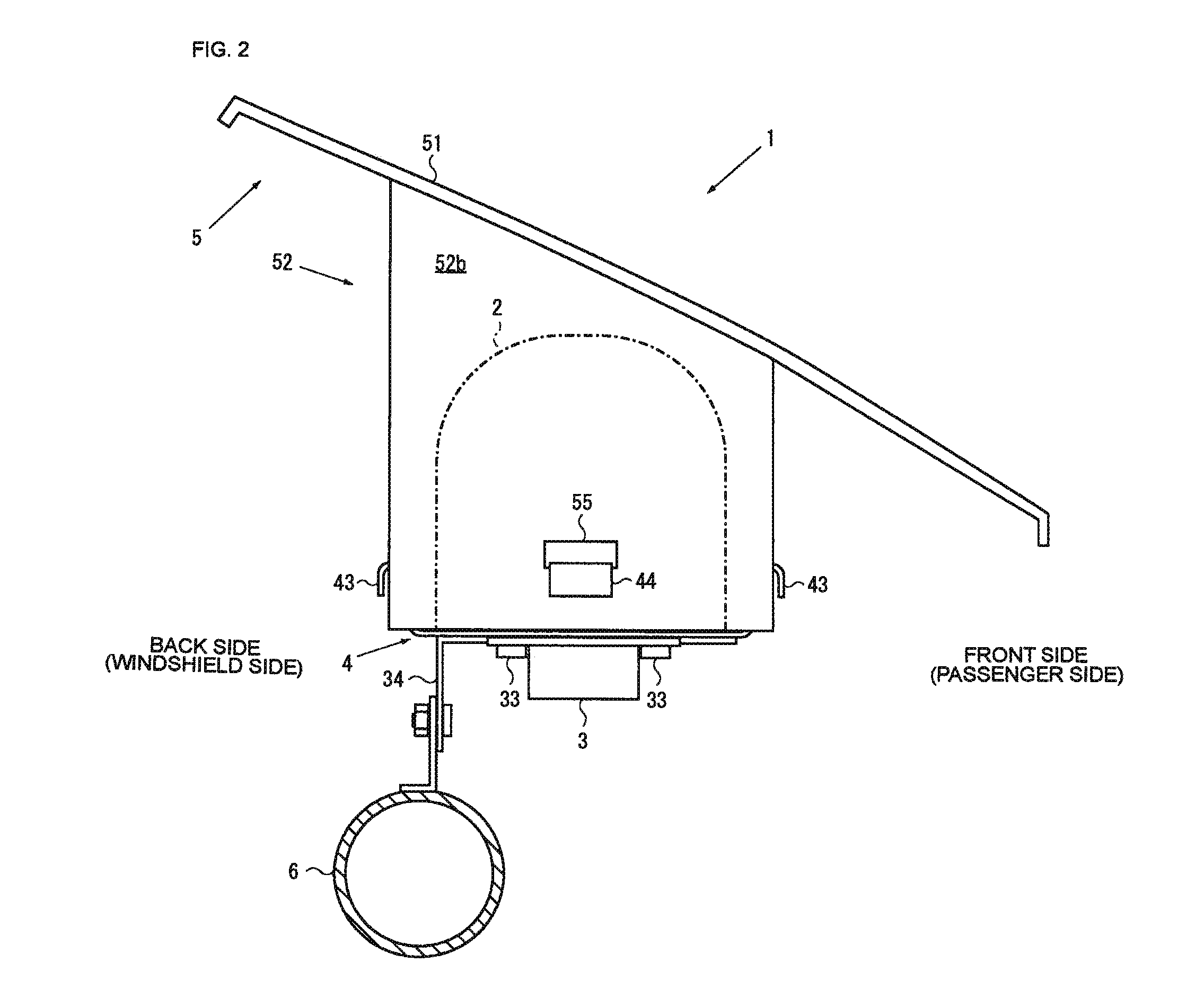
[0035]An airbag device according to an embodiment of the present invention is described below with reference to FIGS. 1 to 9. FIG. 1 is a cross-sectional view of an airbag device according to the present invention. FIG. 2 is a side view of the airbag device illustrated in FIG. 1. FIG. 3 is a back view of the airbag device illustrated in FIG. 1. FIG. 4 illustrates a retainer of the airbag device illustrated in FIG. 1, wherein FIG. 4(A) is a plan view, FIG. 4(B) is a front view, FIG. 4(C) is a plan view of a modification of the retainer, and FIG. 4(D) is a front view of the modification. FIG. 5 illustrates an airbag of the airbag device illustrated in FIG. 1 in an initial stage of inflation and deployment of the airbag, wherein FIG. 5(A) is a cross-sectional view, FIG. 5(B) is an enlarged view of a B portion illustrated in FIG. 4(A).

[0036]As illustrated in FIGS. 1 to 5, according to the first embodiment of the present invention, an airbag device 1 includes an airbag 2 that is normally...

second embodiment

[0056]As illustrated in FIG. 6, an airbag device 11 includes the engagement member 43 formed from a holding belt 45 that is inserted into the holding hole 53, is formed into a ring shape, and is connected to the retainer 4. As illustrated in FIGS. 6(A) and 6(B), the holding belt 45 is fixed to the first side wall portions 42a of the retainer 4. For example, the holding belt 45 is formed from a high-strength belt-like woven, such as webbing used for sheet belts. By using webbing for the holding belt 45 in this manner, a holding belt having such strength that it can endure inflation and deployment of the airbag 2 can be easily obtained.

[0057]In particular, since the holding belt 45 having a length of 10 to 30 cm is sufficient and, in addition, the holding belt 45 is not viewable by an occupant, a tag of webbing or a defective webbing (e.g., the holding belt 45 with bad looking or ragged end) generated in the manufacturing step of a seat belt device can be used as the holding belt 45....

third embodiment

[0063]As illustrated in FIG. 7, an airbag device 12 includes the engagement member 43 formed from the holding belt 45 and the retainer 4 having a fixing portion for the holding belt 45. The fixing portion includes a raised portion 47 that expands outwardly so that part of a fixing member (the rivet 46) for the holding belt 45 does not protrude inwardly beyond the side surface portion (the first side wall portion 42a) on which the fixing portion is disposed.

[0064]More specifically, as illustrated in FIGS. 7 and 9, the raised portion 47 is formed so that part of the first side wall portion 42a of the retainer 4 expands outwardly, and a space protruding outwardly is formed. A top end of the fixing member (e.g., the rivet 46) is inserted into the space formed inside the raised portion 47. As a result, the top end of the fixing member (e.g., an internal head portion 46a of the rivet 46) does not protrude inwardly beyond the first side wall portion 42a.

[0065]Accordingly, by fixing the h...


PUM


Abstract

An airbag device capable of preventing a fish-mouth phenomenon and reducing the weight of a retainer is provided. The inner case has a plurality of holding holes for holding the retainer. The retainer has a bottom surface portion for supporting an airbag and an inflator, a side wall portion that is disposed at the outer periphery of the bottom surface portion and that has a height set to H so that the side wall portion hardly receives a pressure of the airbag when the airbag is inflated and developed, and engagement members that are disposed on the side wall portion and that are engageable with the holding holes. The substantially entirety of the retainer is housed in the inner case when the engagement members are engaged with the holding holes.

Description

CROSS-REFERENCE TO RELATED APPLICATIONS[0001]This application is a U.S. national phase application filed under 35 U.S.C.§371 of International Application PCT / JP2012 / 057095, filed on Mar. 21, 2012, designating the United States, which claims priority from Japanese Patent Application No. 2011-075199, filed Mar. 30, 2011, which are hereby incorporated herein by reference in their entirety.TECHNICAL FIELD[0002]The present invention relates to an airbag device and, in particular, to an airbag device capable of preventing deformation of a retainer during inflation and deployment of an airbag.BACKGROUND ART[0003]In general, vehicles, such as motor vehicles, have an airbag device mounted therein. The airbag is inflated and deployed inside the vehicle to absorb an impact force applied to an occupant in emergency, such as collision or sudden deceleration. Such an airbag device generally includes an airbag that is normally folded and is inflated and deployed in emergency, an inflator for suppl...

Claims


Application Information

Patent Timeline
Patent Type & Authority Patents(United States)
IPC IPC(8): B60R21/205B60R21/217B60R21/16
CPCB60R21/205B60R21/217
Inventor HAYASHI, SHINJIKITAIKE, YUTAKA
Owner JOYSON SAFETY SYST JAPAN KK
Why Eureka
Try Eureka