Connector having shielding piece

A connector and matching connector technology, which is applied in the direction of connection, parts of the connection device, electrical components, etc., can solve problems such as increasing the size of the connector

Inactive Publication Date: 2004-03-10
JAPAN AVIATION ELECTRONICS IND LTD
View PDF0 Cites 8 Cited by
  • Summary
  • Abstract
  • Description
  • Claims
  • Application Information

AI Technical Summary

Problems solved by technology

In this case, increasing the size of the connector

Method used


Image

  • Connector having shielding piece
  • Connector having shielding piece
  • Connector having shielding piece

Examples


Embodiment Construction

[0032] In order to facilitate the understanding of the present invention, before describing the embodiments of the present invention, refer to the attached Figures 1 to 3 , first, an electrical connector according to a conventional technology will be described.

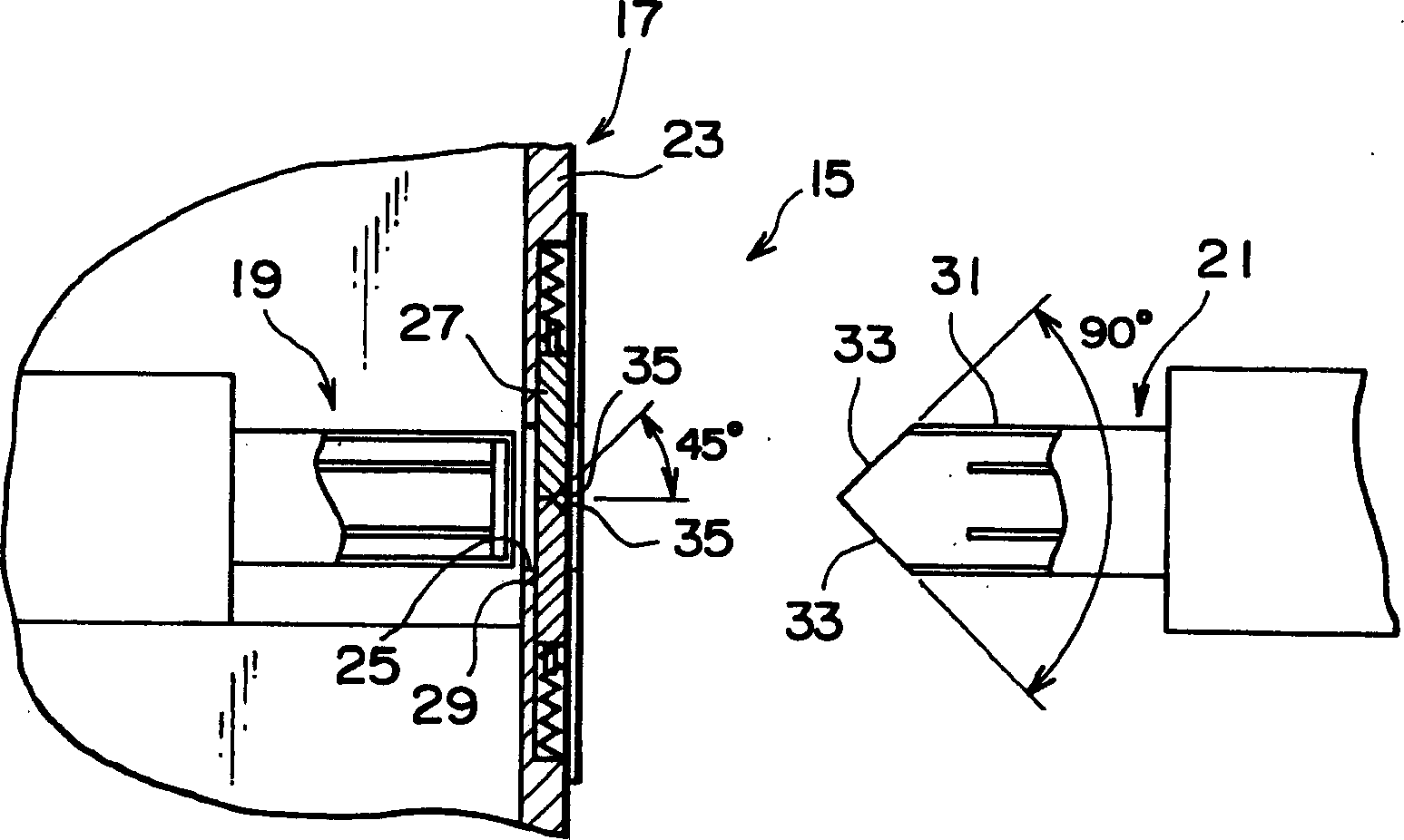
[0033] refer to figure 1 , the connector system 15 according to the conventional technique 1 includes: a pair of connectors composed of a main element side connector 19 and a connection side connector 21 provided in the electronic device main element 17 . The connector system 15 is used to connect to transmit signals between electronic devices. The housing 23 of the electronic device main unit 17 has an opening 25 for accommodating the connection-side connector 21 . Dustproof shutters 27 and 29 are provided at the opening 25 , and the shutters 27 and 29 can be opened and closed in a direction perpendicular to the insertion direction of the connection-side connector 21 . The connection side connector 21 has a guide...


PUM


Abstract

A shuttered connector according to the present invention includes a fitting part that receives a mating connector, an insulator, at least one shutter that is rotatably supported by and fixed on the insulator, and helical springs that continuously urge the shutter in the closing direction. The shutter is selectively in a closed state when the shutter covers the fitting part and in an opened state when the mating connector is capable of being fitted with the shuttered connector. The mating connector includes insertion parts. The shutter further includes guide units. The insertion parts and the guide units cooperate to rotate the shutter in order to open the shutter so that the mating connector is capable of being fitted with the shuttered connector.

Description

technical field [0001] The present invention relates to a connector with a shroud having at least one shroud or at least one door at a fitting portion where a mating connector is fitted. Background technique [0002] Contact portions or contacts for electrical connection in an interface connector are used in commonly used devices including electrical circuits and are exposed to the surrounding environment. Therefore, substances such as dust and dirt may adhere to the contact portion, and these substances may affect the conductivity of the contact portion. Furthermore, coins and the like may enter the contact portion, and these objects are likely to physically damage the contact portion. [0003] In conventional techniques, a cover called a dust cover is mainly used in order to prevent dust, dirt and the like from entering the contact portion and preventing damage to the contact portion. [0004] However, the dust cap must be used when the connector is disconnected, and the...

Claims


Application Information

Patent Timeline
Patent Type & Authority Applications(China)
IPC IPC(8): H01R13/52H01R13/453
CPCH01R13/4532H01R13/52
Inventor 黑木佳英
Owner JAPAN AVIATION ELECTRONICS IND LTD
Why Eureka
Try Eureka