New energy automobile charging pile
A technology of new energy vehicles and charging piles, which is applied in the direction of electric vehicle charging technology, charging stations, electric vehicles, etc., can solve the problems of easy wear and tear of charging lines, fixed positions, and easy safety accidents, so as to prevent easy wear or accidents Accidents, time saving, and work efficiency improvement effects
- Summary
- Abstract
- Description
- Claims
- Application Information
AI Technical Summary
Problems solved by technology
Method used
Image
Examples
specific Embodiment approach 1
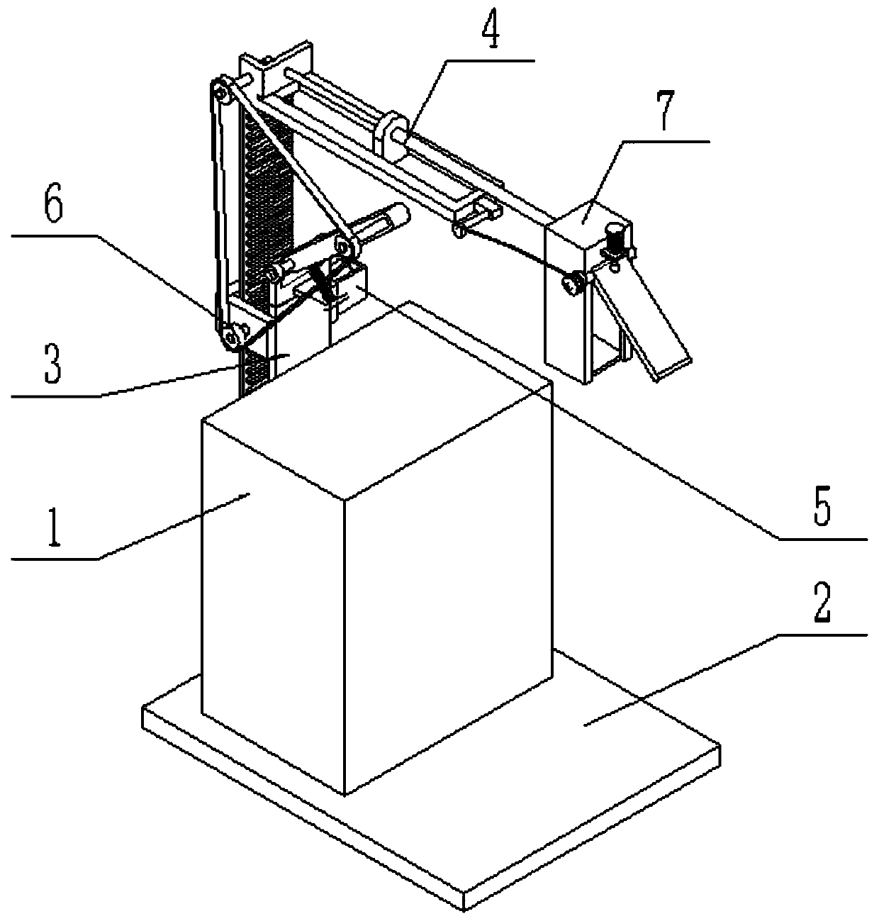
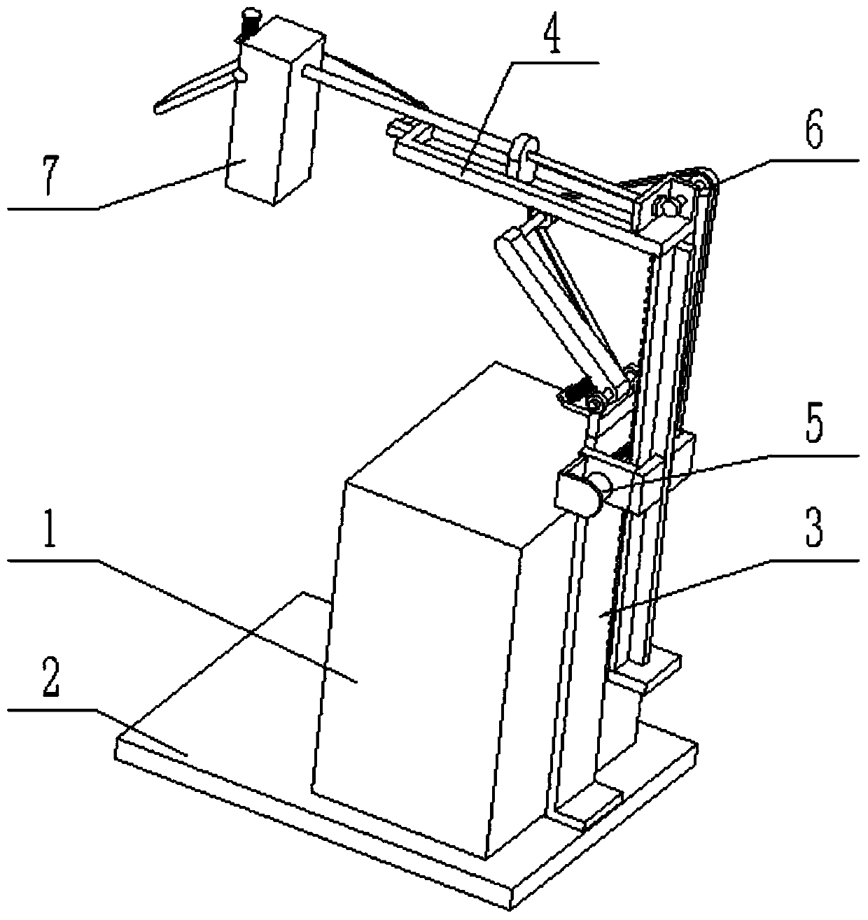
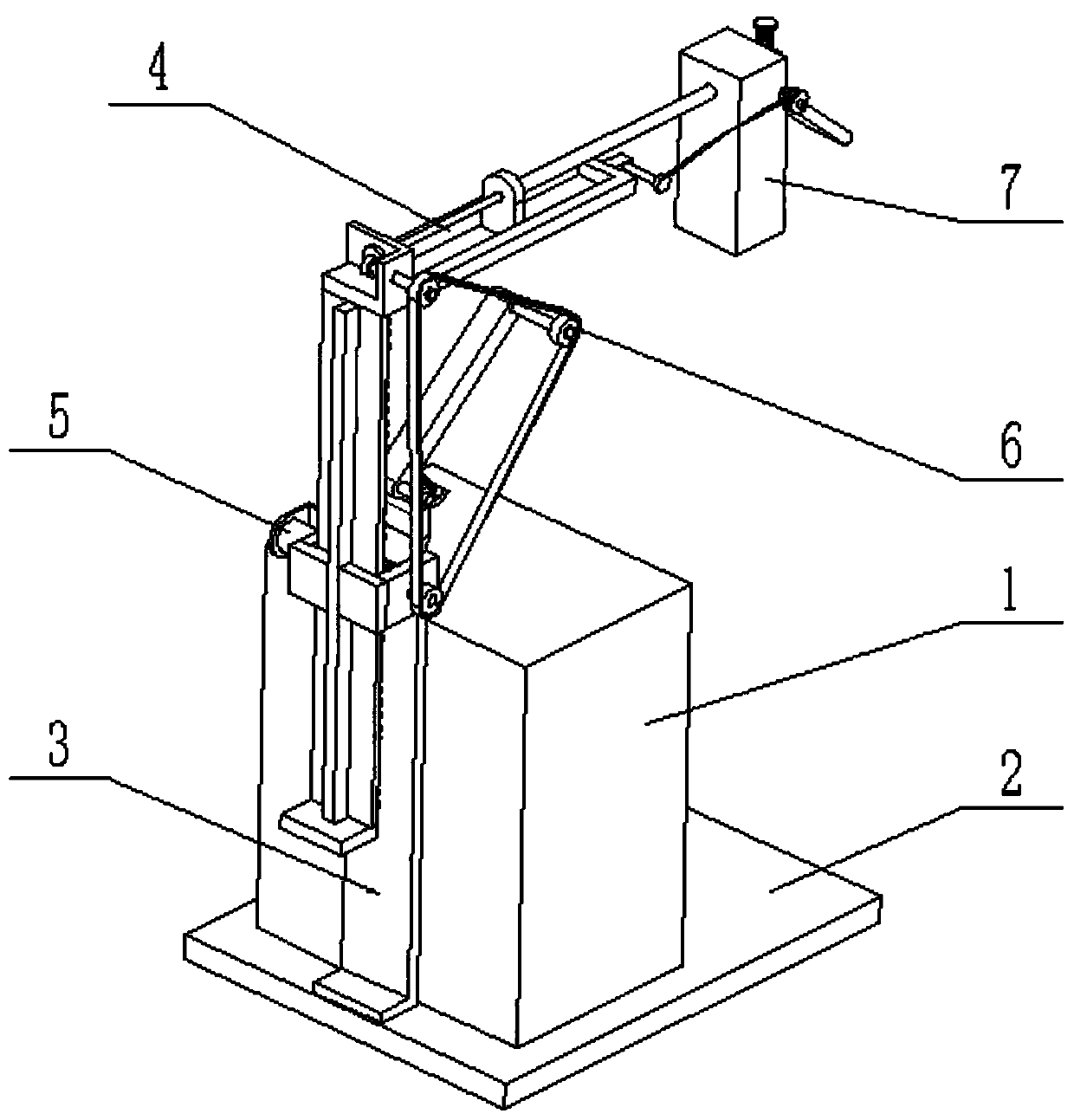
[0025] like Figure 1-10As shown, a new energy vehicle charging pile includes a charging pile body 1, a base plate 2, a lifting bracket assembly 3, a telescopic horizontal frame assembly 4, a drive control device 5, a tension transmission wheel assembly 6, and a charging gun storage box assembly 7 and the charging gun body, the charging pile body 1 is fixedly connected to the base plate 2; the lifting bracket assembly 3 is fixedly connected to the base plate 2; The upper end, the other end of the telescopic horizontal frame assembly 4 is fixedly connected to the charging gun storage box assembly 7; the drive control device 5 is connected to the lifting bracket assembly 3, and the drive control device 5 is connected to the lifting bracket assembly 3 by transmission; the drive control device 5 Connect the tension transmission wheel assembly 6, the tension transmission wheel assembly 6 is connected to the telescopic horizontal frame assembly 4; the lower end of the tension transm...
specific Embodiment approach 2
[0027] like Figure 1-10 As shown, the lifting bracket assembly 3 includes a fixed frame plate 3-1, an L-shaped side frame plate 3-2, a T-shaped slide plate 3-3, a rack 3-4 and a limit plate 3-5; the fixed frame The lower end of the plate 3-1 is fixedly connected to the base plate 2; two L-shaped side frame plates 3-2 are fixedly connected to the fixed frame plate 3-1, and the two L-shaped side frame plates 3-2 are arranged symmetrically on the fixed frame plate 3-1. Both sides of the frame plate 3-1; the outer side of the T-shaped slide plate 3-3 is slidingly fitted and connected between two L-shaped side frame plates 3-2; the inner side of the T-shaped slide plate 3-3 is fixedly connected to the rack 3-4; the bottom end of the T-shaped slide plate 3-3 is fixedly connected to the limit plate 3-5; the rack 3-4 is meshed and connected to the drive control device 5, and the drive control device 5 is fixedly connected to an L-shaped side frame on the plate 3-2; the upper end of ...
specific Embodiment approach 3
[0029] like Figure 1-10 As shown, the telescopic horizontal frame assembly 4 includes a horizontal chute frame 4-1, an L-shaped shaft frame plate 4-2, a transmission shaft 4-3, a transmission bevel gear 4-4, a passive bevel gear 4-5, an external thread Rotary shaft 4-6, guide slide plate 4-7 and internal thread push-pull casing 4-8; L-shaped shaft frame plate 4-2 is fixedly connected on the horizontal chute frame 4-1; the horizontal chute frame 4-1 Fixedly connected to the upper end of the T-shaped slide plate 3-3; the transmission shaft 4-3 is rotatably connected to the L-shaped shaft frame plate 4-2 through a bearing with seat, and one end of the transmission shaft 4-3 is fixedly connected to the tensioning transmission wheel assembly 6. The other end of the transmission shaft 4-3 is fixedly connected to the transmission bevel gear 4-4, the transmission bevel gear 4-4 meshes with the passive bevel gear 4-5, and the passive bevel gear 4-5 is fixedly connected to the external...
PUM
 Abstract
Description
Claims
Application Information
 - R&D
- Intellectual Property
- Life Sciences
- Materials
- Tech Scout
- Unparalleled Data Quality
- Higher Quality Content
- 60% Fewer Hallucinations
Browse by: Latest US Patents, China's latest patents, Technical Efficacy Thesaurus, Application Domain, Technology Topic, Popular Technical Reports.
© 2025 PatSnap. All rights reserved.Legal|Privacy policy|Modern Slavery Act Transparency Statement|Sitemap|About US| Contact US: help@patsnap.com


