
Electric flower ikebana device

A flower and electronic technology, applied in lighting devices, artificial flowers, decorative arts, etc., can solve problems that have not been studied yet, and achieve the effect of disassembly and shipment

Inactive Publication Date: 2004-03-31
廖欣宇 +1
View PDF0 Cites 2 Cited by
  • Summary
  • Abstract
  • Description
  • Claims
  • Application Information

AI Technical Summary

Problems solved by technology

[0002] At present, the art of flower arrangement is more important in flower arrangement, but how to use the circuit to realize the electronic position exchange of a single flower is still a subject that has not yet been studied

Method used


Image

  • Electric flower ikebana device
  • Electric flower ikebana device
  • Electric flower ikebana device

Examples


Embodiment Construction

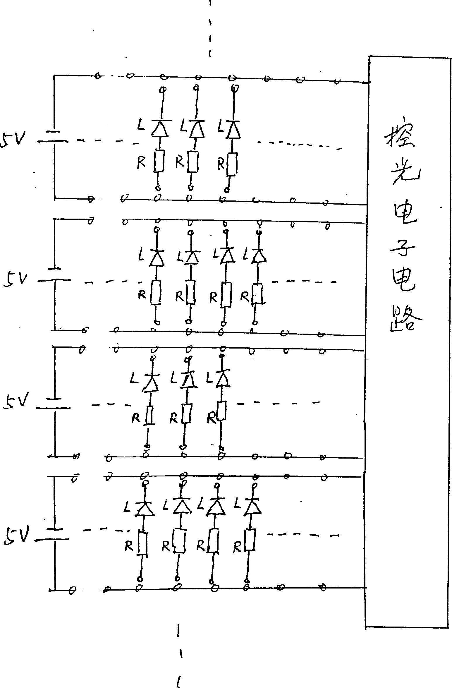
[0014] A pluggable flower with a light-emitting diode (LED) light source and a matching resistor is arranged in the seat box of the flower bush type diffuser; an upper decorative support plate is arranged; a lower light control circuit socket board is arranged. A single electronic flower forms an independent load circuit in a parallel circuit group through a light-emitting diode and a resistor.

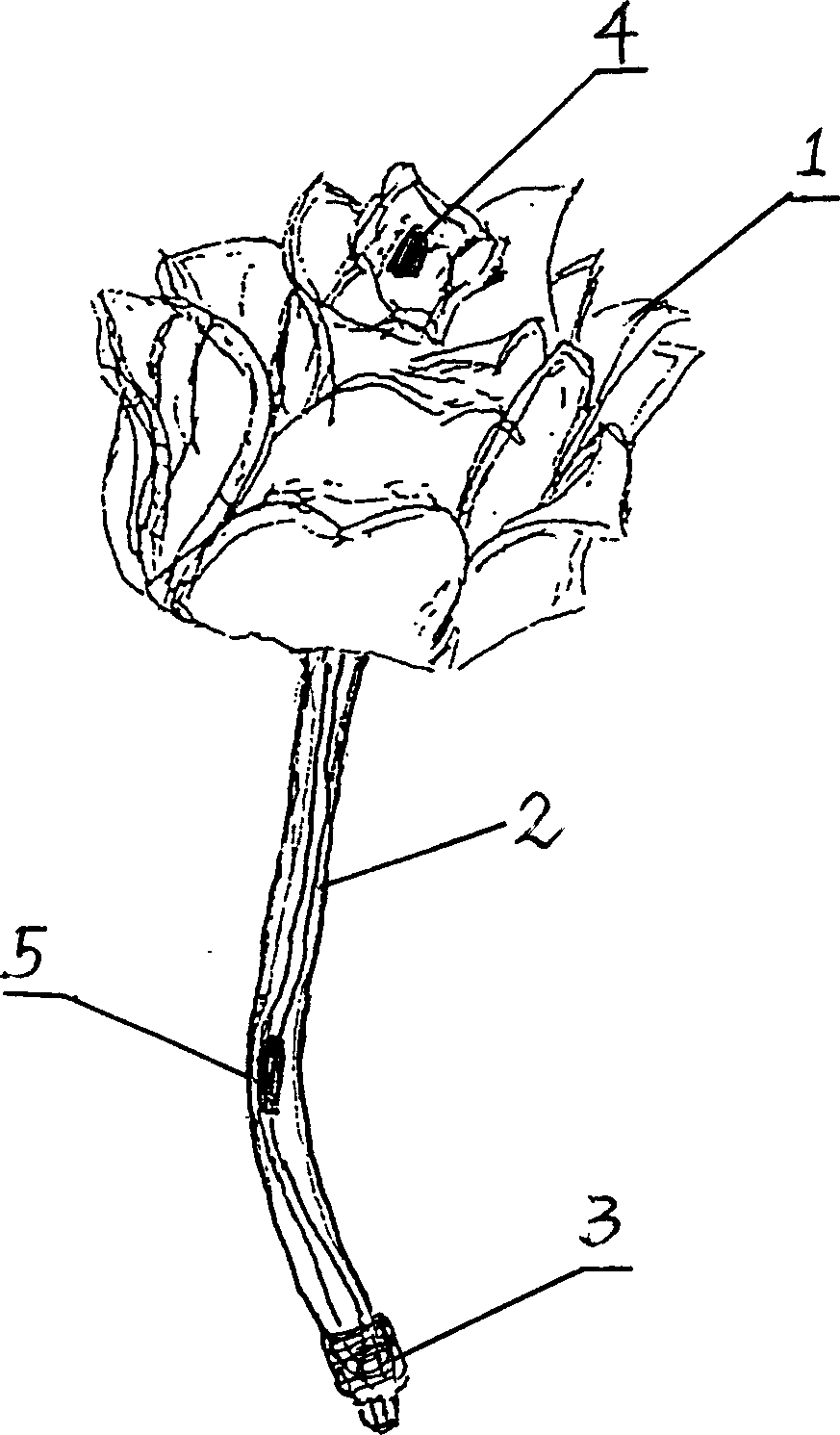
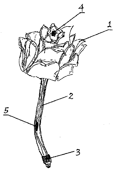
[0015] The single electronic flower is constituted as a whole and can be divided into: flower (1), flower stem (2), circuit plug connector (3), light emitting diode (4) and matching resistor (5).

[0016] Wherein: the flower core (1) is equipped with a light-emitting diode (4) as a light source, the flower pole (2) adopts a hollow plastic tube, and the resistance (5) connected in series with the light-emitting diode (4) is placed on the plastic flower pole (2) At the same time, the circuit plug joint (3) at the other end of the flower bar (2) passes through the hollow plastic flower b...


PUM


Abstract

A detachable electronic device for inserting or pulling flowers. It comprises:1. a bundle of insertable or pullable flowers with a LED power and matching resistors; 2. An upper decorating supporting plate;3. a lower light-controlled circuit socket plate. A single electronic flower could form an independent load circuit by a LED and a resistor, then realizing inserting or pulling electronic a single flower without influencing the overall effect of electronic flowers.

Description

Technical field: [0001] The invention relates to a flower cluster type incense diffuser manufactured by simulating a real flower arrangement technique. Background technique: [0002] At present, the art of flower arrangement is more particular about flower placement, but how to use circuits to realize the position exchange of electronic single flowers is still a subject that has not yet been studied. Invention content: [0003] The object of the present invention is to provide a flower arrangement method and device for simulating potted flowers—an electronic flower arrangement device. [0004] The technical scheme of the present invention is as follows. [0005] A detachable electronic flower plugging and unplugging device is provided in the seat box (or lamp holder) of the flower cluster type diffuser: 1. A pluggable plug-in device with a light-emitting diode (LED) light source and a matching resistor; Pull out flowers; 2. The upper decorative support board; 3. The lowe...

Claims


Application Information

Patent Timeline
Patent Type & Authority Applications(China)
IPC IPC(8): A41G1/00A41G1/02B44C5/06
CPCA41G1/005F21W2121/00F21Y2101/02F21Y2115/10
Inventor 廖欣宇朱振廖可庆
Owner 廖欣宇
Learn More