Eureka AIR delivers breakthrough ideas for toughest innovation challenges, trusted by R&D personnel around the world.

Multi-section compression type rotary compressor and set-up method of discharge volume ratio

A rotary compressor and compression technology, applied in the direction of rotary piston machinery, mechanical equipment, rotary piston pump, etc., can solve the problems of increased operation time and increased processing steps.

Inactive Publication Date: 2004-04-07
SANYO ELECTRIC CO LTD
View PDF0 Cites 0 Cited by
  • Summary
  • Abstract
  • Description
  • Claims
  • Application Information

AI Technical Summary

Problems solved by technology

Moreover, because the eccentricity of the rotary shaft of the first rotary compression assembly and the second rotary compression assembly is different, the rotary shaft needs to be processed in sections, and the processing steps increase
[0012] Therefore, the following problems arise, such as the increase of working time accompanying the change of parts, and the cost incurred due to the change of parts (including changes in material types, processing equipment, measuring instruments, etc.)

Method used


Image

  • Multi-section compression type rotary compressor and set-up method of discharge volume ratio
  • Multi-section compression type rotary compressor and set-up method of discharge volume ratio
  • Multi-section compression type rotary compressor and set-up method of discharge volume ratio

Examples


Embodiment Construction

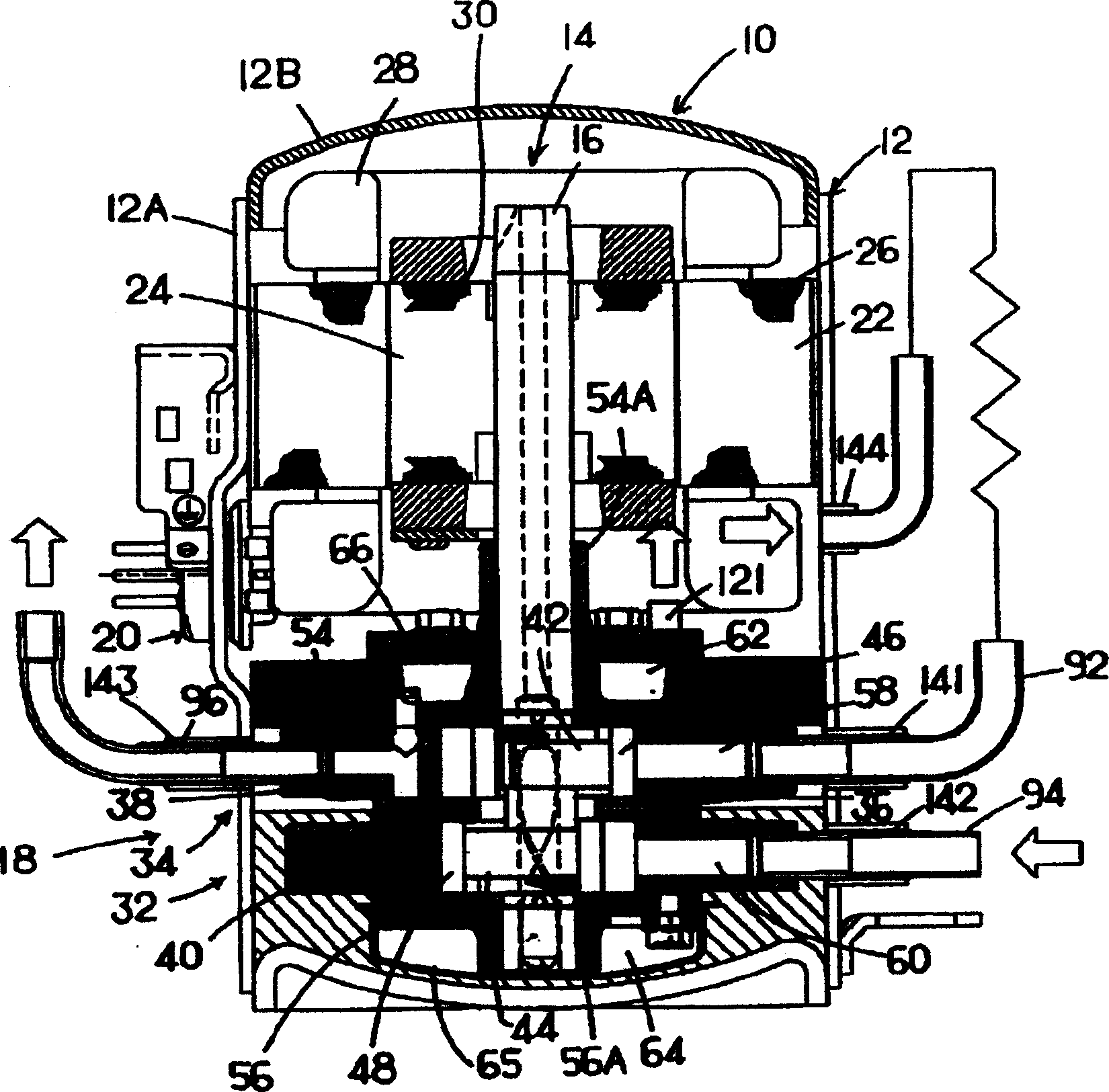
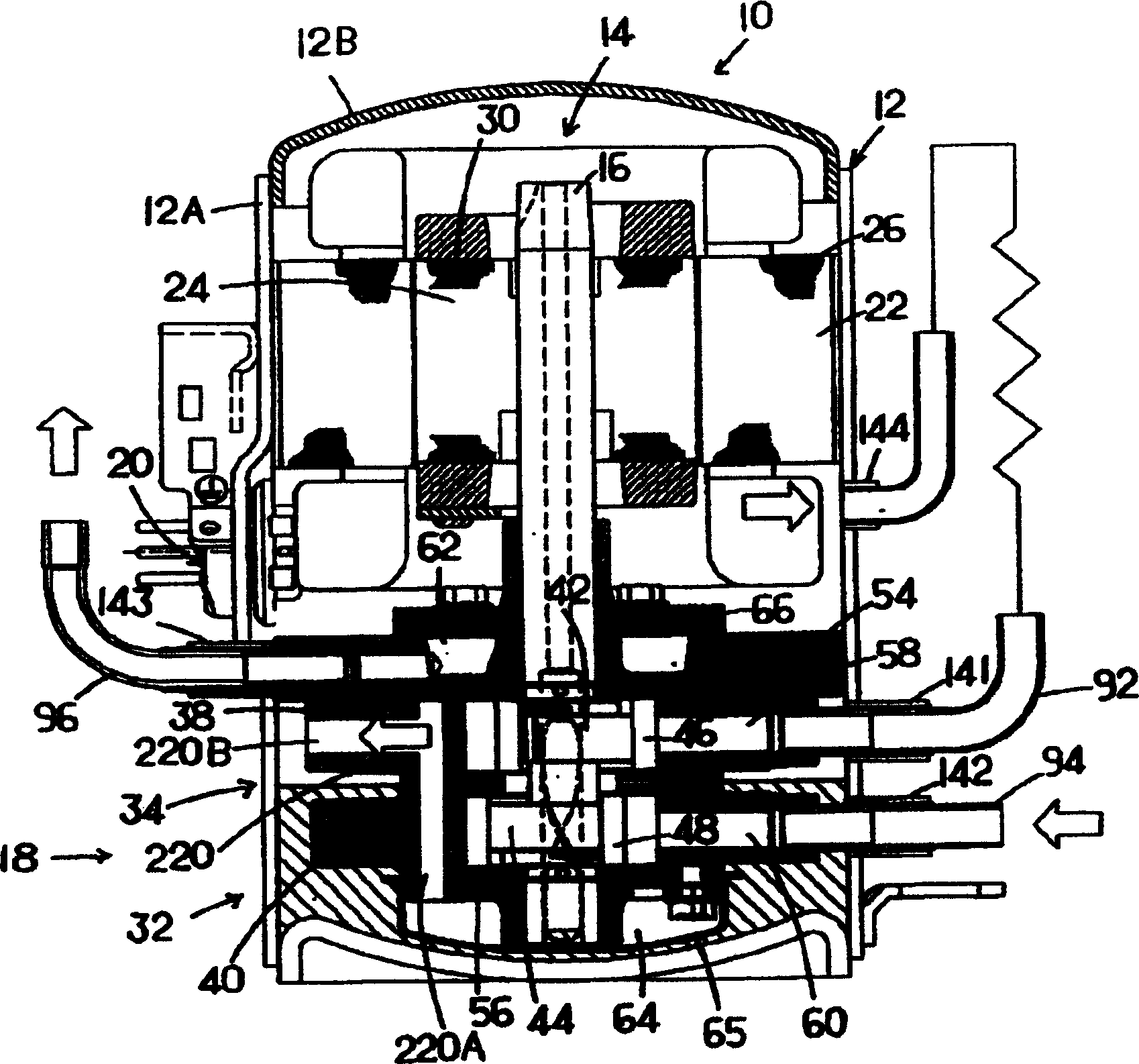
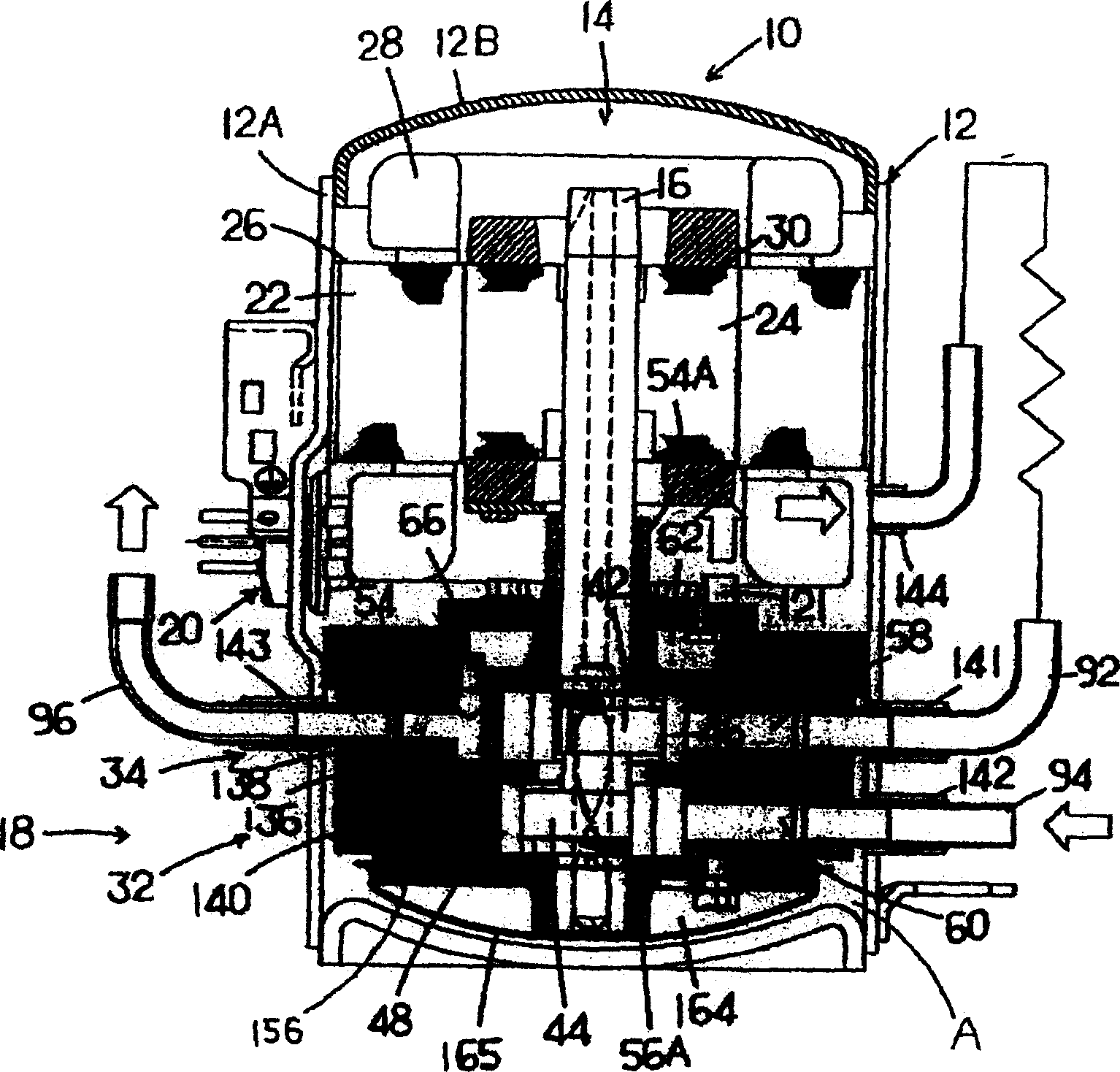
[0061] Next, embodiments of the present invention will be described in detail based on the attached drawings. figure 1 A longitudinal section view of a multi-stage compression rotary compressor according to a preferred embodiment of the present invention is shown. The internal intermediate pressure type multi-stage (two-stage) compression rotary compressor 10 includes first and second rotary compression elements 32 , 34 .

[0062] exist figure 1 In the figure, the rotary compressor 10 of the embodiment is an internal intermediate pressure type multi-stage compression rotary compressor using propane (R290) as a refrigerant. This multi-stage compression rotary compressor 10 is composed of the following components: a cylindrical airtight container body 12A made of steel plates and a bowl-shaped end cap (cover) that closes the upper opening of the airtight container body 12A 12B forms the airtight container 12 as the housing, the electric element 14 arranged on the upper side ...


PUM


Abstract

A multi-stage compression type rotary compressor (10) is provided with an electrical-power element (14), the first and second rotary compression elements (32, 34) driven by a rotary shaft (16) of the electrical-power element (14) in a sealed vessel (12). The refrigerant compressed by the first rotary compression element (32) is compressed by the second rotary compression element (34). The refrigerant is combustible. The refrigerant compressed by the first rotary compression element (32) is discharged to the sealed vessel (12). The discharged medium pressure refrigerant is compressed by the second rotary compression element (34). Additionally, the displacement volume ratio of the second rotary compression element (34) to the first rotary compression element (32) is set not less than 60% and not more than 90%.

Description

technical field [0001] The present invention relates to a multi-stage compression rotary compressor and a method for setting the excluded volume ratio thereof. The multi-stage rotary compressor is equipped with an electric component located in a closed container, and the first motor driven by the rotary shaft of the electric component 1 and the second rotary compression assembly, and the refrigerant compressed by the first rotary compression assembly is compressed by the second rotary compression assembly, and the refrigerant gas compressed and discharged by the first rotary compression assembly is sucked into the second rotary compression assembly, Spit out with compression. Background technique [0002] This kind of known rotary compressor sucks the refrigerant gas from the suction port of the rotary compression assembly into the low-pressure chamber side of the cylinder, and then compresses it by the action of the rollers and blades, and discharges it from the discharge p...

Claims


Application Information

Patent Timeline
Patent Type & Authority Applications(China)
IPC IPC(8): F04C18/344F04C18/356F04C23/00
CPCF01C21/0863F04C18/3564F04C23/001F04C23/008F04C18/344
Inventor 松本兼三藤原一昭山崎晴久渡部由夫山口贤太郎津田德行山中正司里和哉
Owner SANYO ELECTRIC CO LTD
Why Eureka
Eureka Blog
Learn More