gear unit

A technology of gear devices and gears, which is applied in the direction of gear transmissions, transmissions, transmission parts, etc., can solve the problem of suppressing the amount of lubricant that is difficult to seal, and achieve the effect of reducing the amount of seals

Active Publication Date: 2020-10-02
SUMITOMO HEAVY IND LTD
View PDF8 Cites 0 Cited by
  • Summary
  • Abstract
  • Description
  • Claims
  • Application Information

AI Technical Summary

Problems solved by technology

[0007] However, in this gear unit, since only the parallel-shaft gear set of the output stage is arranged in a separate chamber, there is a problem that it is difficult to design a small amount of lubricant.

Method used


Image

  • gear unit
  • gear unit
  • gear unit

Examples


Embodiment Construction

[0019] Hereinafter, an example of an embodiment of the present invention will be described in detail with reference to the drawings.

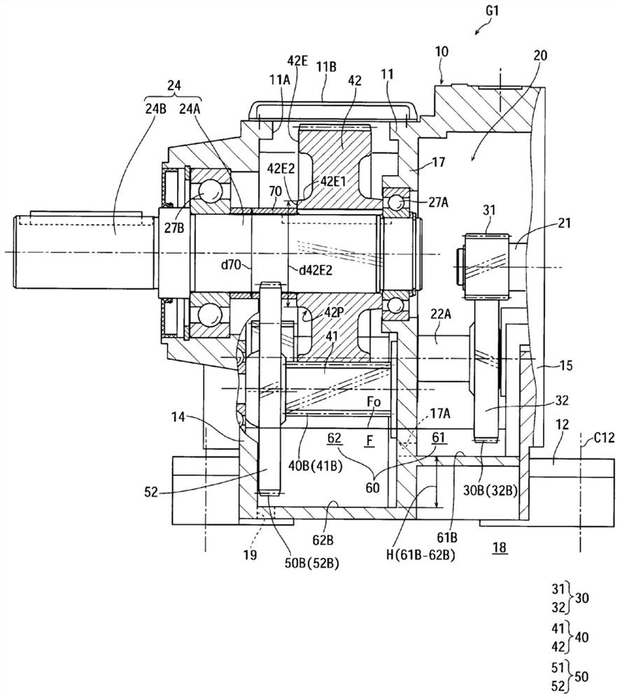
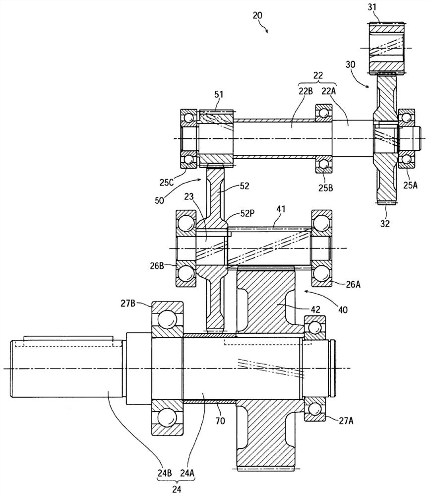
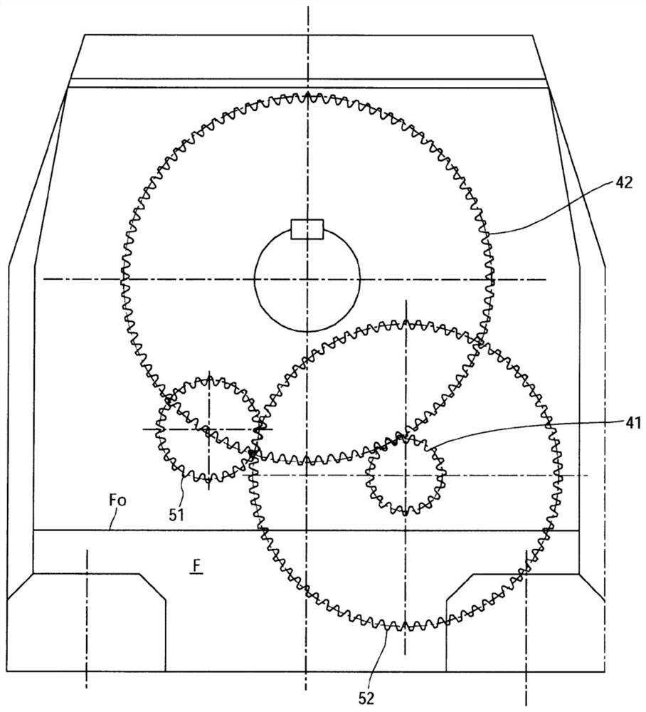
[0020] figure 1 It is a cross-sectional view of a gear device according to an example of an embodiment of the present invention, figure 2 is an expanded plan view showing the power transmission system of the gear unit, image 3 It is a side view showing the arrangement position of each gear of the gear unit. 4(A) and FIG. 4(B) are diagrams showing only a part of the gear unit, and FIG. 4(A) is a cross-sectional view showing the arrangement state of the input gear and the intermediate pinion assembled on the second shaft. , FIG. 4(B) is a cross-sectional view showing the arrangement state of the intermediate gear and the output pinion assembled on the third shaft.

[0021] The gear unit G1 includes a housing 10 and a reduction mechanism 20 housed in the housing 10 .

[0022] The housing 10 of the gear unit G1 is formed in a substantially cu...


PUM


Abstract

The invention provides a gear device which can more easily realize packaging amount reduction of lubricant. The gear device (G1) is provided with a housing (10) and a speed reducing mechanism (20) which is accommodated in the housing, wherein the speed reducing mechanism is provided with an input-grade parallel shaft gear set (30), an output-grade parallel shaft gear set (40), and an intermediate-grade parallel shaft gear set (50) which is arranged between the input-grade parallel shaft gear set and the output-grade parallel shaft gear set. The housing is provided with a first accommodating chamber (61) for accommodating the input-grade parallel shaft gear set, and a second accommodating chamber (62) for accommodating the intermediate-grade parallel shaft gear set and the output-grade parallel shaft gear set.

Description

[0001] This application claims priority based on Japanese Patent Application No. 2015-221676 filed on November 11, 2015. The entire contents of this Japanese application are incorporated herein by reference. technical field [0002] The invention relates to a gear device. Background technique [0003] Patent Document 1 discloses a gear device including a case and a reduction mechanism housed in the case. [0004] The speed reduction mechanism of the gear device includes an input stage parallel shaft gear set, an output stage parallel shaft gear set, and an intermediate stage parallel shaft gear set disposed between the input stage and the output stage. [0005] The casing is provided with a partition wall, and a parallel shaft gear set of an output stage that requires high support strength is arranged in a separate chamber (second storage chamber) formed by partitioning the partition wall. [0006] Patent Document 1: Chinese Utility Model Patent No. 201627905 Gazette [0...

Claims


Application Information

Patent Timeline
Patent Type & Authority Patents(China)
IPC IPC(8): F16H1/20F16H57/023F16H57/04
CPCF16H1/20F16H57/023F16H57/0457
Inventor 为永淳
Owner SUMITOMO HEAVY IND LTD
Why Eureka
Try Eureka