Production method of rib fabric portion

A technology of knitted parts and ribs, which is applied in the field of manufacturing rib knitted parts, and can solve problems such as roughness and bulkiness

Active Publication Date: 2004-05-12
KARL MAYER STOLL R&D GMBH
View PDF0 Cites 6 Cited by
  • Summary
  • Abstract
  • Description
  • Claims
  • Application Information

AI Technical Summary

Problems solved by technology

But in any case, the rib knit part is much rougher and bulkier than the jersey part

Method used


Image

  • Production method of rib fabric portion
  • Production method of rib fabric portion
  • Production method of rib fabric portion

Examples


Embodiment Construction

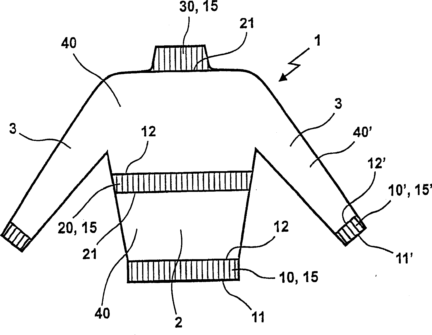
[0032] figure 1 Shown is a knitted pullover made from tubular finished fabric having rib knit sections 10 and 10' starting at the torso and arms, another rib knit section 20 in the mid-torso area and rib knit at the neck Part 30. The torso portion 2 is formed by a jersey knit portion 40 between the rib knit portions 10 , 20 and 30 . The arm 3 above the cuff 10' is also formed from a jersey portion 40. Reference numerals 11, 11' designate the initial knitting course of the cuff 10, 10' and 12, 12' designate the transitional knitting course of the jersey portion 40, 40'. 15, 15' represent ribbed knitting courses. In the rib knit parts 20 and 30 , 21 designates the transition area from the plain knit part 40 to the rib knit parts 20 , 30 . 12 and 12' again indicate the transition zone from the rib knit portion 20, 10' to the jersey knit portion 40, 40'.

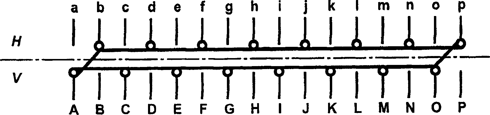
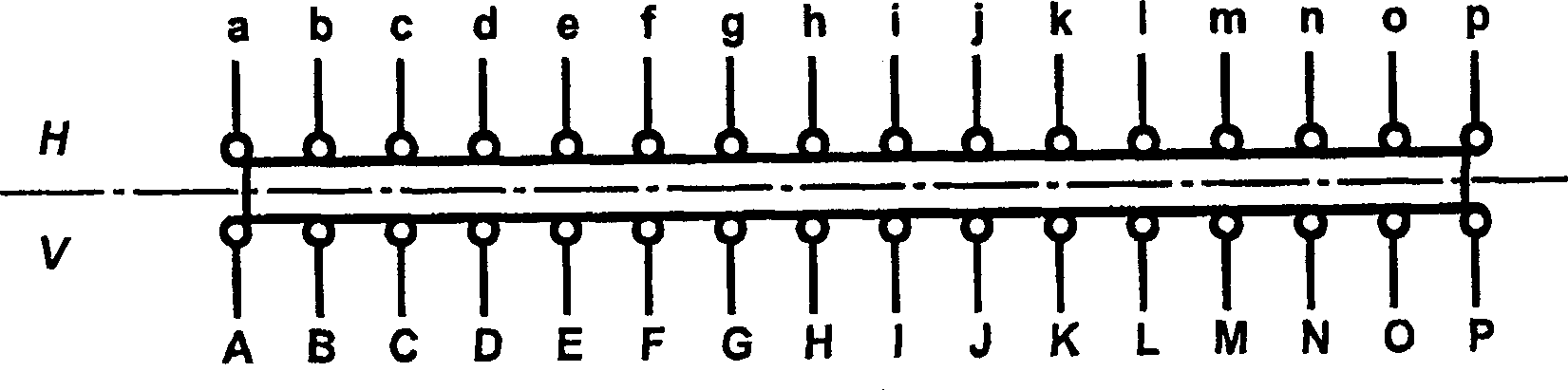
[0033] figure 2 Shown is a typical needle arrangement for forming a tubular finished knitted fabric, characterized...


PUM


Abstract

In a textile knitting process to make the ribbed section forming part of a hosiery garment, a mesh is formed by each needle forming part of the non-ribbed section, on a flatbed knitting machine esp. having two facing needle beds. The visible aspect of the rib-knitted section is formed by one, or two neighbouring plain stitches, following which two needles form no stitches. To create the reverse stitch on the needles on the opposing needle bed, one needle forms a reverse stitch and a second needle forms no stitch.

Description

technical field [0001] The invention relates to a method for producing rib-knitted parts on tubular fabrics, in which stitches are formed by needles in non-rib-knitted regions on a linen knitting machine having at least two needle beds located opposite one another. Background technique [0002] For tubular fabrics, in which the stitches are formed by at most the second needle, rib knit sections can be formed relatively easily due to the presence of free needles necessary for the transfer process to achieve the desired rib knitting needle arrangement. For tubular fabrics formed by all needles, free needles are not used, it is more difficult to form the arrangement of the knitting needles of the rib-knitted part. According to the prior art method, at least each second needle must be released from the coil. Likewise, the rib-knitted fabric is knitted with each second needle, however, the rib-knitted portion exhibits a coarser mesh in contrast to the adjoining or preceding plai...

Claims


Application Information

Patent Timeline
IPC IPC(8): D04B1/22D04B1/24
CPCD04B1/102D04B1/22D04B1/24D04B1/246
Inventor T·施托尔H·施密德特A·乌尔默
Owner KARL MAYER STOLL R&D GMBH
Why Eureka
Try Eureka