flexible first-layer configuration of radio interface for connecting radio to PLMN
A radio block and wireless communication device technology, applied in the first layer and its interaction with higher layers, can solve the problems of physical layer consumption, high cost, and complex memory
- Summary
- Abstract
- Description
- Claims
- Application Information
AI Technical Summary
Problems solved by technology
Method used
Image

Examples
Embodiment Construction
[0051] The present invention allows custom and / or optimized layer one transport channels to be configured while a given call is being established. These layer one transport channels may for example be configured in such a way as to best support the traffic associated with the call.
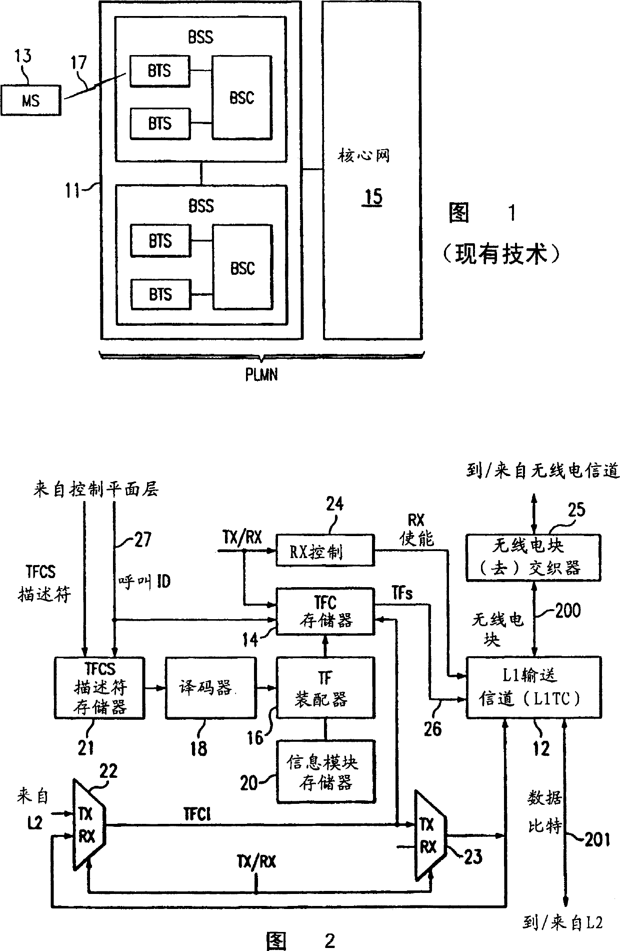
[0052] Figure 2 schematically shows relevant parts of an exemplary embodiment of a radio transceiver according to the invention, such as a radio transceiver in a mobile station of the kind shown generally as 13 on Figure 1, or in Figure 1 A radio transceiver in a Base Transceiver Station (BTS) of the kind shown generally above. The transceiver portion shown in Figure 2 is typically located at the first layer (physical or PHY layer) of the transceiver. A plurality of layer one transport channels (L1TC) 12 transfer data bits bidirectionally at 201 with layer two (L2). The layer one transport channel 12 also bidirectionally transfers radio blocks with the radio block interleaver / deinterleaver 25 in...
PUM
 Abstract
Description
Claims
Application Information
PatSnap Eureka turns technology decisions into work you can execute. Powered by our Innovation Knowledge Graph, it runs expert workflows across engineering, life sciences, materials and intellectual property. Get your review-ready output in minutes.


