Method of displaying video images on plasma display panel and corresponding plasma display panel

A video image, plasma technology, applied in static indicators, instruments, etc., can solve problems such as integration errors

Inactive Publication Date: 2004-05-12
INTERDIGITAL CE PATENT HLDG
View PDF1 Cites 1 Cited by
  • Summary
  • Abstract
  • Description
  • Claims
  • Application Information

AI Technical Summary

Problems solved by technology

Different distributions of gray levels are also possible, but there will always be integration errors

Method used


Image

  • Method of displaying video images on plasma display panel and corresponding plasma display panel
  • Method of displaying video images on plasma display panel and corresponding plasma display panel
  • Method of displaying video images on plasma display panel and corresponding plasma display panel

Examples


Embodiment Construction

[0023] What has been described above will no longer be described below Figure 1 to Figure 3 Give a detailed explanation.

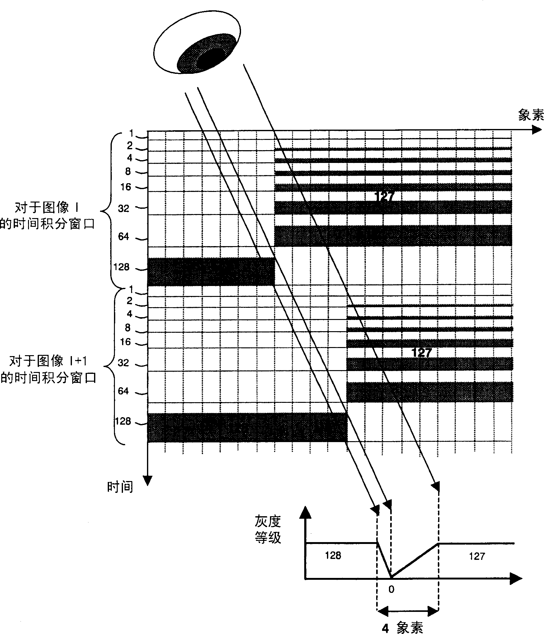
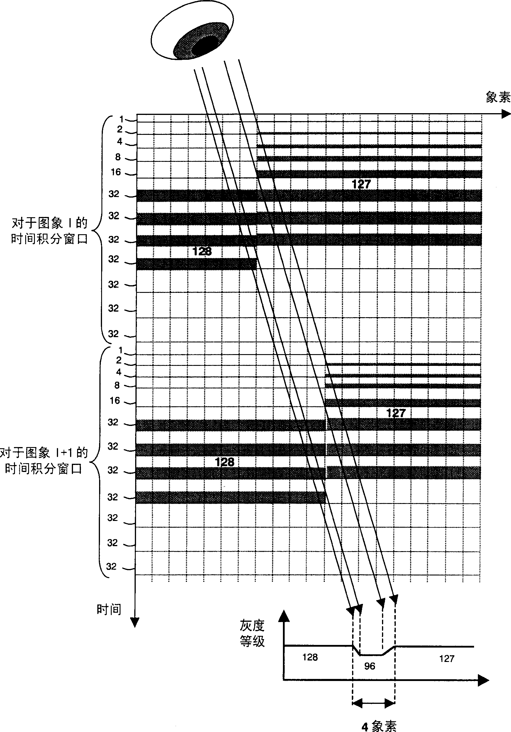
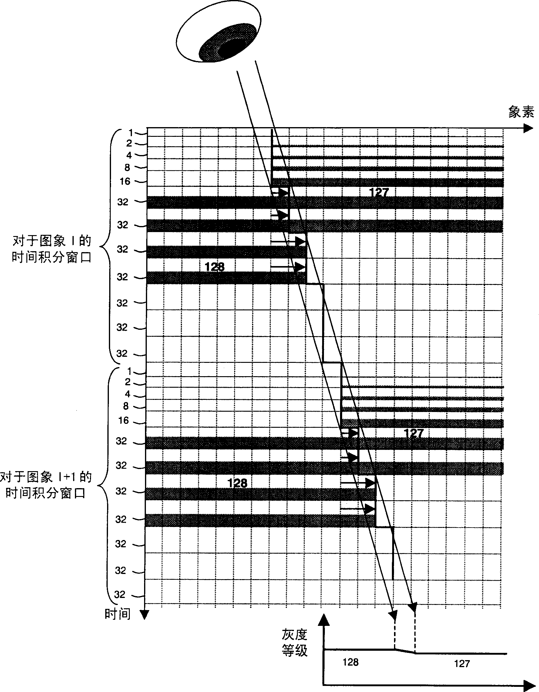
[0024] According to the invention, the sub-scans are arranged in a symmetrical manner in the time-integration window of the image to be displayed, and half of the sub-scans are spatially displaced in order to counteract the delineation defects produced by the other half of the sub-scans. A particular sub-scanning arrangement produces defects specific to that arrangement. If the particular arrangement of sub-scans is inverted in time, the defects will be inverted in space. The display of two consecutive groups, one of which is symmetrical to the other, is compensated until the two groups are aligned with the direction causing the defect. To make compensation and implementation simpler, it is preferable to use a pyramidal code that can be separated into two groups, one of which is symmetrical with respect to the other. A pyramidal code is defined as a co...


PUM


Abstract

The present invention relates to a method of displaying video images on a plasma display panel. The invention is applicable in plasma display panels. According to the invention, in order to achieve contouring movement compensation, the subscans are divided into two symmetrical groups of subscans. Moreover, the movement of the video image to be displayed with respect to the preceding video image is estimated so as to generate a movement vector for each pixel of the video image. Finally, for each pixel of the video image, the subscans of the second group are displaced by an amount proportional to the estimated movement vector.

Description

technical field [0001] The present invention relates to a method of displaying video images on a plasma display panel, and more particularly, the present invention relates to a display device comprising a matrix of elementary cells, wherein the elementary cells can be either in an on state, or is off. Background technique [0002] Plasma Display Panel (PDP) technology enables large, flat displays. A PDP generally includes two flat insulating tiles defining a gas-filled space therebetween, and in the gas-filled space, a basic space bounded by a barrier is defined. A basic unit corresponds to a basic space provided on each side of said basic space having at least one electrode. To activate the elementary cells, a discharge is generated in the corresponding elementary spaces by applying a voltage between the cell electrodes. Thereafter, the discharge causes emission of ultraviolet rays in the elementary cells. Phosphors deposited on the walls of the cells convert ultraviole...

Claims


Application Information

Patent Timeline
IPC IPC(8): G09G3/20G09G3/28G09G3/291G09G3/296
CPCG09G2320/0266G09G2320/106G09G3/204G09G3/2033G09G2320/0261G09G3/28G09G3/291G09G3/296
Inventor 迪迪埃·杜瓦扬埃贝尔·赫尔泽曼恩乔纳森·克维克
Owner INTERDIGITAL CE PATENT HLDG
Why Eureka
Try Eureka