Paralled switch device

A technology of switch components and motors, which can be used in emergency protection devices, electric switches, transportation and packaging, etc., and can solve problems such as hindering vehicles

Inactive Publication Date: 2004-05-19
ORMON CORP
View PDF0 Cites 0 Cited by
  • Summary
  • Abstract
  • Description
  • Claims
  • Application Information

AI Technical Summary

Problems solved by technology

However, on the other hand, this countermeasure will lead to an i

Method used


Image

  • Paralled switch device
  • Paralled switch device
  • Paralled switch device

Examples


Embodiment Construction

[0053] Hereinafter, embodiments of the present invention will be described in detail with reference to the drawings.

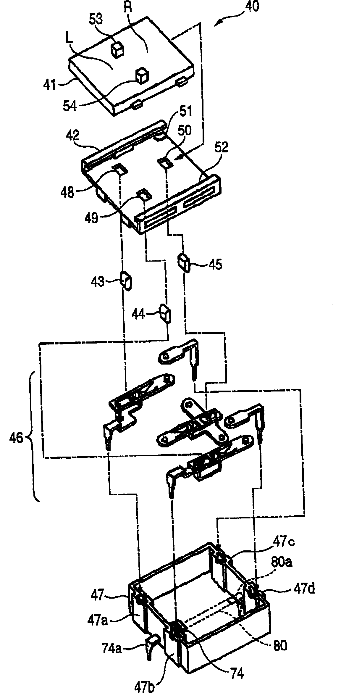
[0054] figure 1 It is an exploded view of the switch device 40 in this embodiment. According to the order from the top to the bottom of the drawing, the switch device 40 consists of a slider (switch operation part) 41, a slide rail and an upper cover (hereinafter referred to as "the upper cover") 42, three buttons (switch operation parts) 43~ 45, snap-action contact mechanism group 46 and housing 47 constitute. After installing the pre-assembled contact structure group 46 inside the housing 47, use the upper cover 42 that has assembled the three buttons 43-45 and the slider 41 to close the opening on the housing 47, thereby assembling the switch. device 40.

[0055] The upper cover 42 has insertion holes 48 to 50 for the buttons 43 to 45 and slide rails 51 and 52 for holding the slider 41 so as to be slidable in the L direction and the R direction in the d...


PUM


Abstract

A switch unit is provided which is free from causing contact damage even in case applied to a high power voltage, whose switch unit is not greatly increased in size. Switches A and B are to take a motor stop status, a motor forward rotation status and a motor reverse rotation status. A switch C is to electrically connecting and disconnecting between the switches A and B and the power source. This switch C, when the switches A and B transits from the motor forward rotation status or motor reverse rotation status into the motor stop status, is operated from a connection state to a disconnection state at a time of any of completing the transition to the motor stop status and prior to a predetermined marginal period of time.

Description

technical field [0001] The present invention relates to a kind of switch device for the rotation and stop of a DC motor for opening and closing the windows of vehicles such as automobiles or a DC motor similar to this purpose, and particularly relates to a switching device suitable for use in high power supply voltages (such as 42V) The switching device of the DC motor operating under the electrical system of the system). Background technique [0002] The current automobile uses a 14V electrical system, but due to the continuous increase of loaded electronic equipment, the 14V system cannot meet the power consumption. In order to solve the above problems, as a result of global discussions conducted by industry associations, etc., it was agreed that an electrical system of the "42V system", which is a triple high voltage system that considered safety to the human body, was selected. [0003] Electrical devices that can be operated in the 42V system electrical system include,...

Claims


Application Information

Patent Timeline
IPC IPC(8): B60R16/02H01H15/06H01H23/02H01H23/16H01H23/22H02P1/06H02P1/22H02P7/06
CPCH01H2300/01H01H15/06H01H23/164H01H2021/225
Inventor 清水敬一田中康英三好哲彦
Owner ORMON CORP
Why Eureka
Try Eureka