Jetting controller for ink-jet printer, and its control method

A technology for inkjet printers and control devices, applied in printing devices, printing, etc., can solve problems such as deteriorating printing quality and obstructing inkjet volume

Inactive Publication Date: 2004-05-26
SAMSUNG ELECTRONICS CO LTD
View PDF1 Cites 2 Cited by
  • Summary
  • Abstract
  • Description
  • Claims
  • Application Information

AI Technical Summary

Problems solved by technology

These variations prevent uniform inkjet volume, deteriorating print quality

Method used


Image

  • Jetting controller for ink-jet printer, and its control method
  • Jetting controller for ink-jet printer, and its control method
  • Jetting controller for ink-jet printer, and its control method

Examples


Embodiment Construction

[0022] Preferred embodiments of the invention will now be described in detail, examples of which are illustrated in the accompanying drawings, wherein like reference numerals refer to like elements throughout. The embodiments are described below in order to explain the present invention with reference to the figures.

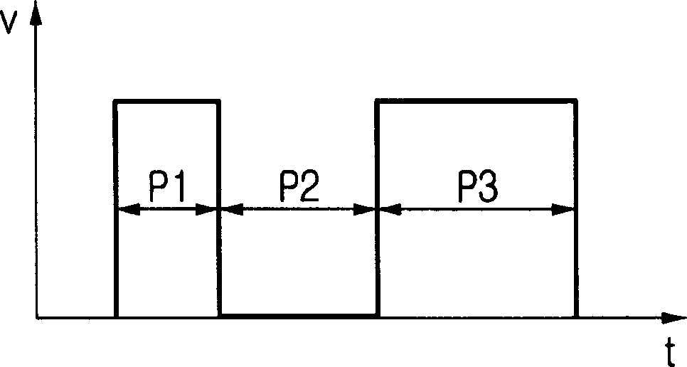
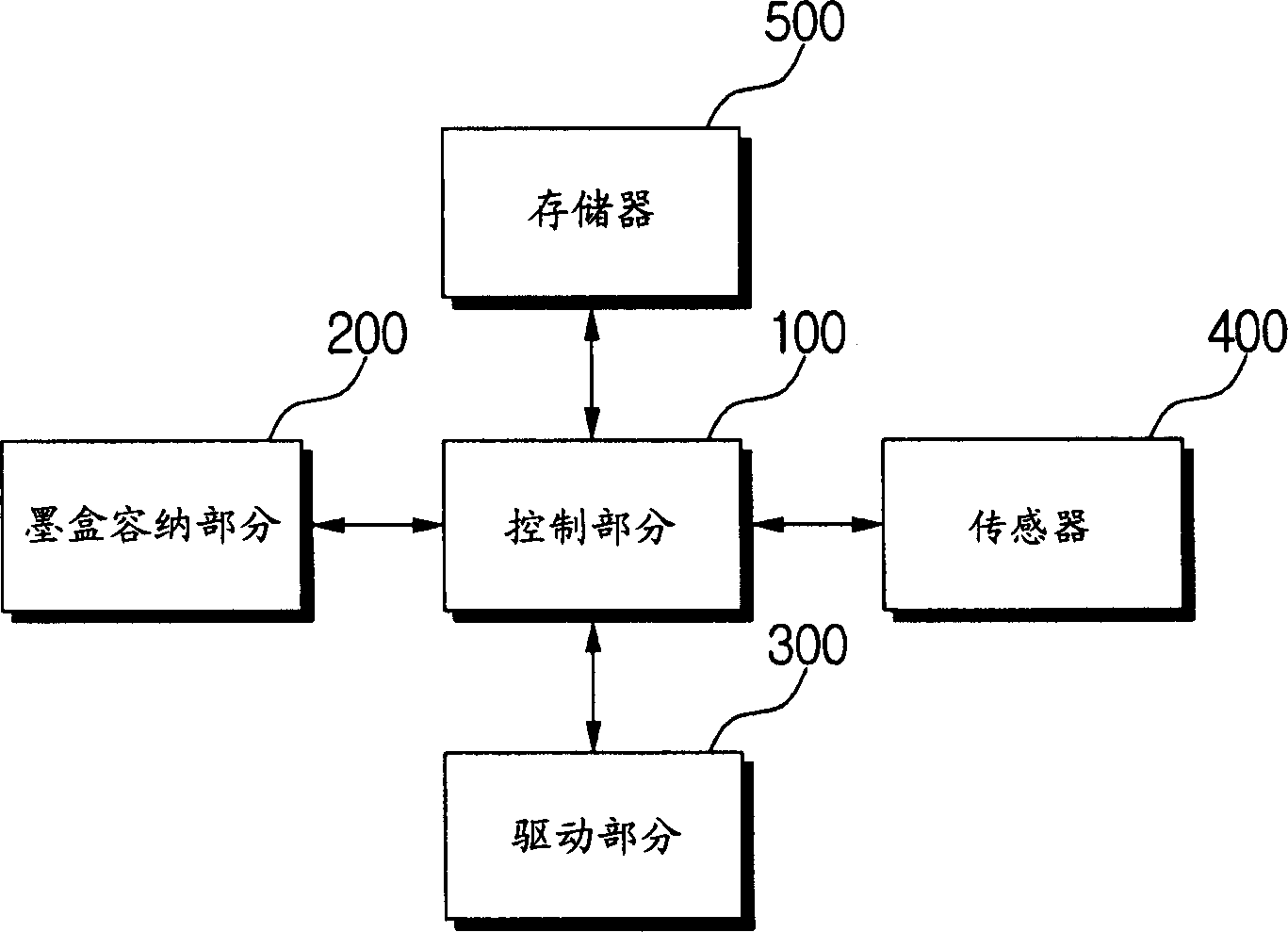
[0023] figure 2 is a block diagram of a control device for an inkjet printer according to an embodiment of the present invention. Such as figure 2 As shown, the control means includes an ink cartridge accommodating portion 200 for accommodating an ink cartridge, a driving portion 300 for driving an ink ejection heater to perform a printing operation, a sensor 400 for sensing a printing density of a printing pattern, setting a width of a pulse to be input into the ink ejection heater and A control section 100 that controls a control device for the inkjet printer as a whole, and a memory 500 for storing an optimum pulse width determined by the control section ...


PUM


Abstract

An injection controlling device for an inkjet printer and a controlling method thereof includes determining whether an ink cartridge is installed in the inkjet printer, printing patterns in order by driving an ink injection heater with an array of predetermined pulses with widths that vary in sequential order in response to the ink cartridge being connected to the inkjet printer, detecting printing densities of the printed patterns; determining the pattern with an optimal density among the printing densities, and storing the width of the pulse corresponding to the pattern with the optimal density as an optimal pulse width.

Description

technical field [0001] The present invention relates to an inkjet printer, and in particular to an ejection control device for the inkjet printer and a control method capable of correctly adjusting the amount of inkjet. This application claims priority from Korean Patent Application No. 2002-67624 filed with the Korean Intellectual Property Office on November 2, 2002, the disclosure of which is incorporated herein by reference. Background technique [0002] A general inkjet printer drives an inkjet heater for ejecting ink in an ink cartridge, thereby printing on a printing medium. The inkjet printer includes a heater driving control unit for controlling the width or waveform of a driving pulse, thereby driving the inkjet heater according to the temperature of an ink cartridge head. [0003] figure 1 Drive pulses for a conventional inkjet heater are shown. P1 denotes a preheating pulse for preheating, P3 denotes a main pulse of the heater, and P2 denotes an interval betwee...

Claims


Application Information

Patent Timeline
Patent Type & Authority Applications(China)
IPC IPC(8): B41J2/05B41J29/393
CPCB41J2/04558B41J2/04593B41J2/0458B41J29/393B41J2/04528B41J2/04591B41J2/04598
Inventor 朱永福任大赫
Owner SAMSUNG ELECTRONICS CO LTD
Why Eureka
Try Eureka