Debarking shaft arrangement for debarking mechanism

A shaft device and bark technology, which is applied to bark, manufacturing tools, wood processing appliances, etc., can solve the problems of inconvenient maintenance and high cost of worn teeth

Inactive Publication Date: 2004-05-26
ANDRITZ AG
View PDF2 Cites 5 Cited by
  • Summary
  • Abstract
  • Description
  • Claims
  • Application Information

AI Technical Summary

Problems solved by technology

[0003] One problem with known peeling mechanisms of the type described abo

Method used


Image

  • Debarking shaft arrangement for debarking mechanism
  • Debarking shaft arrangement for debarking mechanism
  • Debarking shaft arrangement for debarking mechanism

Examples


Embodiment Construction

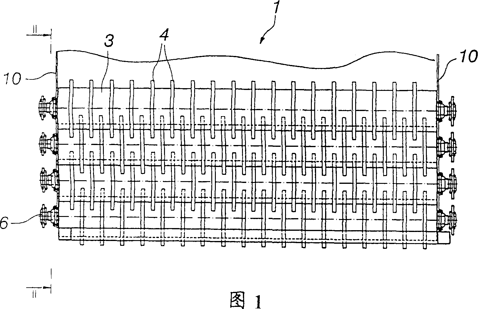
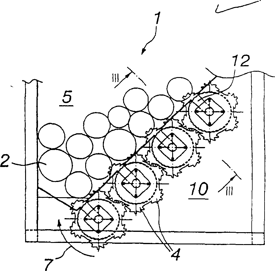
[0014] A debarking mechanism 1 is depicted in the figure for debarking or pre-treatment of trees 2 for final debarking performed separately and for removing at least some of the debarked bark from the timber stream passing through the debarking mechanism.

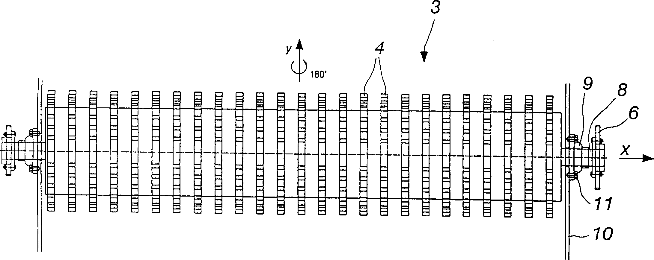
[0015] The debarking mechanism 1 is provided with a plurality of rotatable debarking shafts 3 extending parallel to the feed direction in which the trees 2 are fed. In the illustrated example, each end of the peeling shaft 3 is provided with a sprocket 6, whereby at least one end of the peeling mechanism 1, the sprocket 6 passes through a sprocket chain (not shown). out) to each other and to the gear of an electric motor not shown.

[0016] Said stripping shaft 3 is provided with a plurality of teeth 4 extending beyond the circumferential surface of said shaft 3, said teeth being suitable for stripping the tree 2 being processed transversely to the length of the tree and simultaneously relative to said stripping shaft 3. A...


PUM


Abstract

The invention relates to a debarking shaft arrangement for a debarking mechanism (1), said debarking mechanism (1) being intended for the decortication or pretreatment of trees (2) for separately performed final barking and for the expulsion of at least some of the removed barks from a wood flow passing through the debarking mechanism, said debarking mechanism comprising a number of rotatable debarking shafts (3) extending parallel to the advancing direction of the trees (2) to be fed therethrough and provided with a number of teeth (4) extending beyond the circumferential surface of the shaft (3) and adapted to strip bark off the presently processed trees (2) transversely to the lengthwise direction of the trees and at the same to convey the trees transversely relative to said shafts (3), and said shafts (3), together with the teeth (4) thereof, being adapted to constitute at least a part of a support surface, upon which the presently processed trees (2) travel through the debarking mechanism (1). The teeth (4) are designed to be effective in both rotating directions of said rotatable debarking shafts (3), and the debarking shafts (3) are designed to be pivotable.

Description

technical field [0001] The present invention relates to a debarking shaft arrangement for use in a debarking mechanism for debarking or pre-treating trees for a separate final debarking and for removing at least some of the debarking For bark that falls off, the debarking mechanism comprises a plurality of rotatable debarking shafts extending parallel to the feed direction in which the trees are fed and provided with a plurality of teeth extending beyond the peripheral surface of the shaft, the teeth adapted to align the bark of the tree being processed transversely along the length of the tree and to simultaneously transport the tree laterally relative to the shaft and which, together with its teeth, are adapted to constitute the tree being processed over which it travels. At least a portion of a support surface of the peeling mechanism. Background technique [0002] Peeling mechanisms of the type described above are known, for example, from US patents 4,685,498 and 5,394,...

Claims


Application Information

Patent Timeline
IPC IPC(8): B27L1/00B27L1/02B27L1/10
CPCB27L1/10B27L1/02
Inventor J·哈武迈基P·科科B·柯克帕特里克
Owner ANDRITZ AG
Why Eureka
Try Eureka