Elevator overspeed protection apparatus

A kind of protective equipment and elevator technology, which is applied in the direction of elevators, transportation and packaging, etc. It can solve the problems of inconvenient handling, changes in the displacement of the flat block 17, danger, etc.

Inactive Publication Date: 2004-06-02
MITSUBISHI ELECTRIC CORP
View PDF2 Cites 12 Cited by
  • Summary
  • Abstract
  • Description
  • Claims
  • Application Information

AI Technical Summary

Problems solved by technology

Thus, since the arm 14 often rotates over a large range under normal operating conditions of the car 12, the problem that this conventional safety system for elevators has to solve is that the braking device 20 sometimes breaks down, And the life of the supporting shaft 15 used as a rotating motion bearing part will be shortened.
[0007] Also, in this conventional elevator speed controller, when the car 12 is in motion due to a unilateral load or when the passenger enters the car 12 and swings in the horizontal direction, the magnetic flux in the sensor 16 path passes through the gap (air gap) The distance of the part) changes, and the force produced by the sensor 16 changes simultaneously, so this traditional elevator overspeed protection device must also solve such a problem: the displacement of the flat block 17 also changes, so the detection of the applicable speed of the car 12 becomes Unstable, with the result that brake equipment 20 sometimes fails
[0008] In addition, this type of conventional elevator overspeed protection equipment must also solve the problem that when the car 12 is moving or when passengers enter the car 12, the detection for improving the vibration situation cannot be performed.
[0009] Moreover, this type of traditional elevator overspeed protection device also has to solve such problems: since this type of protection device is located in the compartment 12, it becomes very heavy because it has a large number of mechanical parts that need to occupy a large space. , so its transmission efficiency is low, and it cannot be easily transported
[0010] Have again, this type of traditional elevator overspeed protection equipment also must solve such problem: because what detect is only the running speed of car 12, although car 12 is running at a speed that is not dangerous, it goes beyond the controllable speed. range and enters a low point of the upper limit, at this time, because the dangerous situation cannot be detected, an emergency shutdown cannot be effectively performed, which is very dangerous

Method used


Image

  • Elevator overspeed protection apparatus
  • Elevator overspeed protection apparatus
  • Elevator overspeed protection apparatus

Examples


Embodiment 1

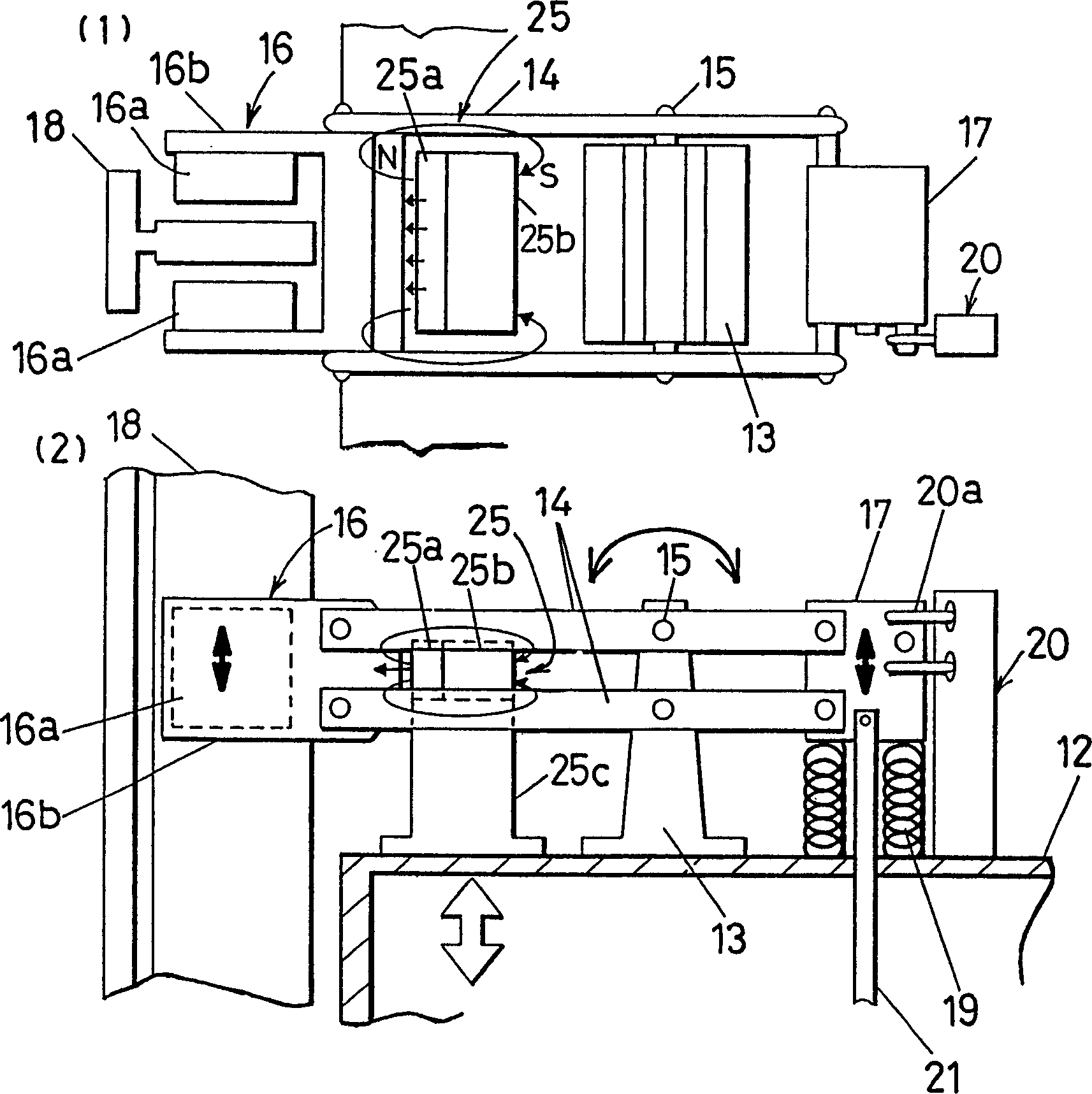
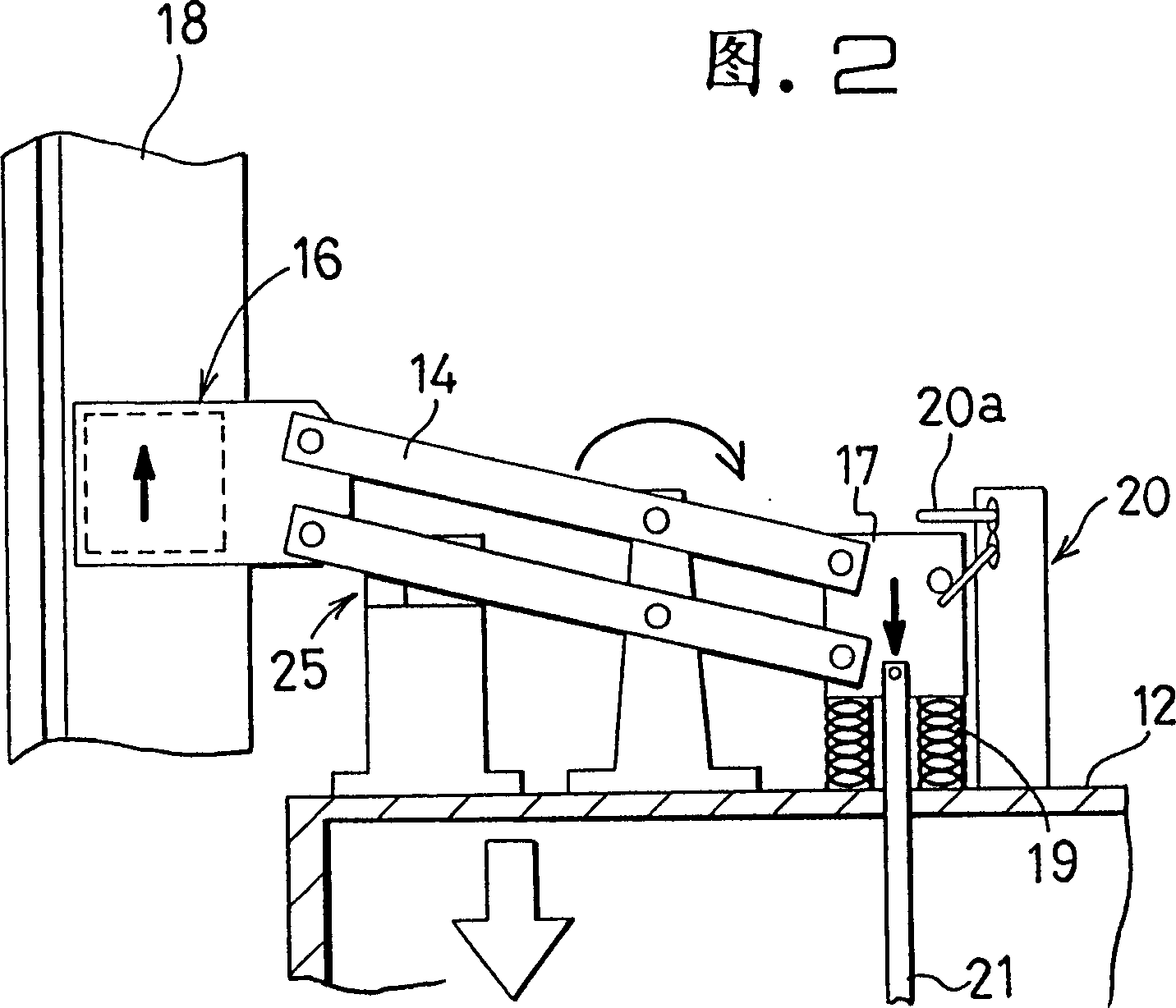
[0219] Referring to Fig. 1 (1) and 1 (2), label 12 refers to the car of an elevator, 13 refers to the base that is located on the car 12, 14 refers to the arm that is formed as a pair of parallel link forms, 15 refers to and is located on the base 13 The fulcrum that is used to support the arm 14 to rotate, 16 refers to the sensor that is rotatably installed on one end of the arm 14 and is used to detect the speed of the compartment 12, 16a refers to a pair of magnets that are arranged in a relative relationship, and 16b refers to fixing the pair of magnets. 17 refers to the counterweight used for balancing with the sensor 16 on the other end of the arm 14, while 18 refers to a conductor that is fixedly arranged along the side of the compartment 12 such as a guide rail, and the magnet from the sensor 16 is connected to the fork frame. The magnetic flux emitted by 16a passes through a plate-shaped portion extending from the center of the conductor 18, toward the carriage 12 and ...

Embodiment 2

[0229] The arm 14 in embodiment 1 is to take the form of parallel link, but in this embodiment 2, as shown in Fig. 6 (1) and 6 (2), arm 14 at this moment is made by connecting sensor 16 and A single link of the counterweight 17 is formed. Due to this structure, the structure of the arm 14 is simplified and can be formed with a reduced number of parts and a reduced cost.

Embodiment 3

[0231] In Embodiment 1, the pair of magnets 16a is arranged on two opposite sides of the conductor 18 so that the conductor 18 is held between the pair of magnets 16a. In Embodiment 3, the pair of magnets 16a is shown in Fig. As shown, it is only arranged on one side of the conductor 18, the structure of the magnetic circuit of the sensor 16 is simplified, and the number of components and the cost can be reduced at the same time. Furthermore, due to the reduced weight of the sensor 16, its dynamic response is improved.


PUM


Abstract

An elevator overspeed protection apparatus includes a brake apparatus which makes use of eddy currents. The brake apparatus includes a magnetic spring placed on a car in the proximity of a pickup of the elevator overspeed protection apparatus such that, when an arm of the brake apparatus is in a horizontal condition, a displacement of the pickup is prevented with a strong attracting force by the magnetic spring, but when the arm is inclined obliquely, the attracting force of the magnetic spring is prevented from acting upon the pickup. Due to the construction, the brake apparatus operates stably and with certainty and has an increased life.

Description

[0001] This application is a divisional application of the patent application with the application number 00119247.7, the application date being November 3, 1995, and the invention title being "Elevator Overspeed Protection Equipment". technical field [0002] The present invention relates to an elevator overspeed protection device, or relates to an elevator controller, which is used to safely operate the elevator to lift people and / or objects. Background technique [0003] Figure 93 (1) and 93(2) are a plan view and a front view respectively, showing a traditional elevator overspeed protection device such as disclosed in Japanese Patent (Open) Application No. Heisei 5-147852. exist Figure 93 (1) and 93 (2), label 12 refers to an elevator car, and 13 refers to a base that is located on the car 12, and 14 is the arm that is formed by a pair of parallel connecting rods, and 15 is provided with on the base 13 and is used for Supporting arm 14 is the fulcrum that rotates, and ...

Claims


Application Information

Patent Timeline
Patent Type & Authority Applications(China)
IPC IPC(8): B66B1/28B66B5/04B66B5/06
CPCB66B5/044B66B5/06
Inventor 汤村敬伊藤和昌
Owner MITSUBISHI ELECTRIC CORP
Why Eureka
Try Eureka