A locking device for a ventilating window

A ventilation window and locking position technology, which is applied to locks operated by mechanical transmission, locks operated by non-mechanical transmission, building locks, etc., can solve the problems of increasing the complexity and cost of installing windows, and achieve the effect of blocking function

Inactive Publication Date: 2004-06-02
VKR HLDG AS
View PDF3 Cites 8 Cited by
  • Summary
  • Abstract
  • Description
  • Claims
  • Application Information

AI Technical Summary

Problems solved by technology

While these solutions achieve a blocking effect and require no user action, avoiding the disadvantages described above, they add significantly to the complexity and cost of manufacturing and / or installing the window

Method used


Image

  • A locking device for a ventilating window
  • A locking device for a ventilating window
  • A locking device for a ventilating window

Examples


Embodiment Construction

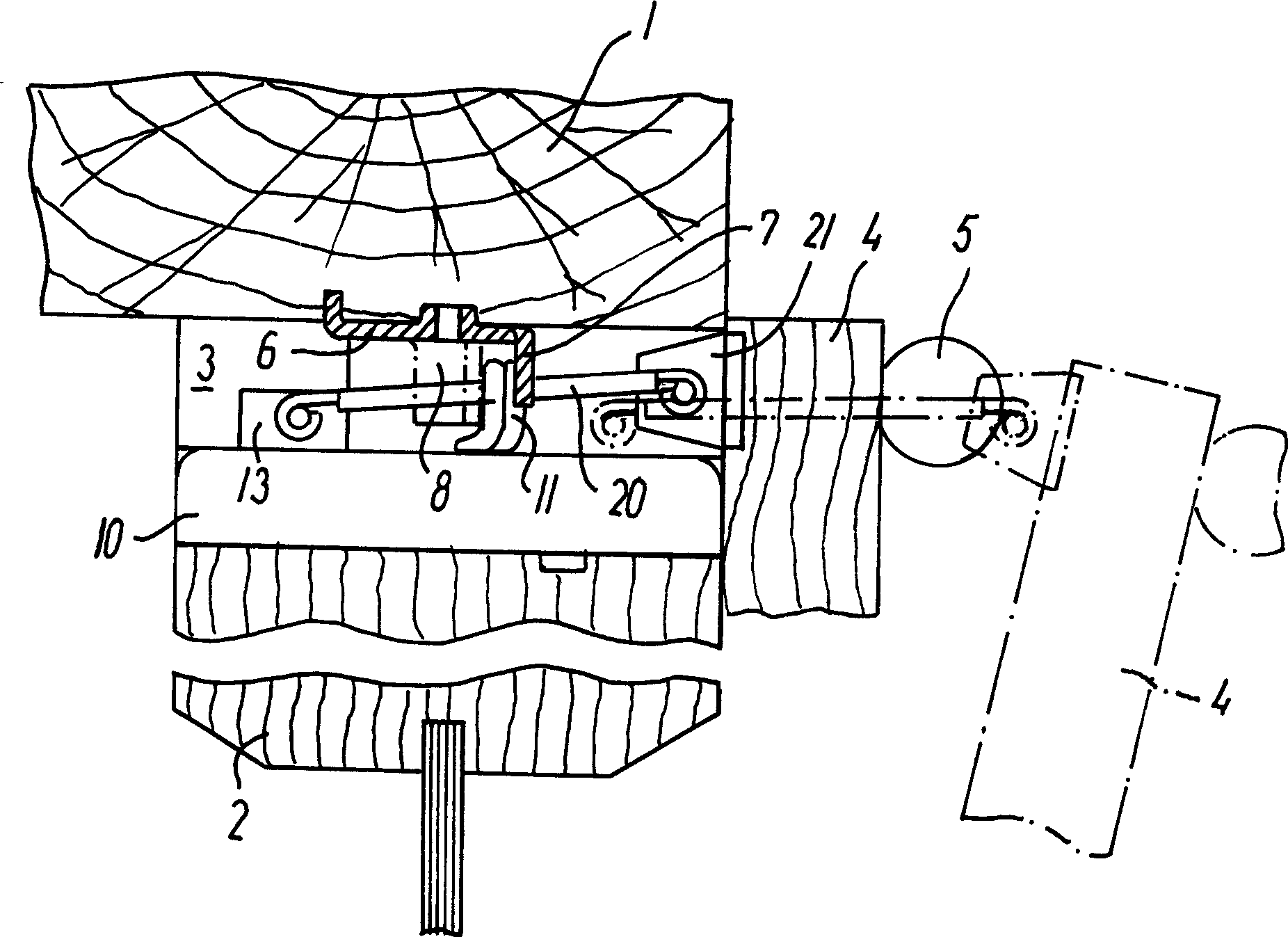
[0024] In Fig. 1, reference numerals 1 and 2 designate, respectively, the top member of the main window frame of the skylight and the top member of the pane supporting the sash, which is installed in the main window frame and can be wound parallel to the top members 1 and 2. Pivot (not shown in the figure) pivots.

[0025] On both sides of the main sash and between the sash top member 1 and 2 there is a gap 3 for mounting the above-mentioned locking assembly by which the sash can be locked in a closed position relative to the main sash. The gap 3 also forms a ventilation channel, when the window sash is in the closed position under the action of the top cover member 4, the air flow between the outside and the inside of the window can flow through the ventilation channel, the length of the top cover member 4 is equal to the width of the window sash, And it is connected with the sash top member 2 positioned on the inner side of the window so as to be able to rotate between a clo...


PUM


Abstract

In a locking assembly for a ventilating window comprising a locking control mechanism connected with an operator member (4) via an actuator slide (13) release of locking engagement between movable and stationary locking members (11, 7) may be blocked by blocking means (26) acting on the locking control mechanism and/or the actuator slide (13). The blocking means (26) is selectively operable by user operated means functionally integrated with the operator member (4) for displacement between a blocking condition, in which the slide (13) is blocked against displacement from an intermediate locking position to a first end position, and a non-blocking condition, in which the slide (13) is freely displaceable by operation of the operator member (4).

Description

technical field [0001] The present invention relates to a locking assembly for a louver of which one sash is openable relative to the main sash by pivotal movement about a pivot parallel to the pair of sash. Background technique [0002] A known design is disclosed in PK-C-114046, wherein the locking assembly comprises a strike plate and a housing with at least one main sash fastened to the pair of sashes The fixed locking member on the component, the housing is fastened on the above-mentioned sash component facing the deadbolt piece. At least one pawl member is mounted on the housing, and the pawl member can move between a locked position and an unlocked position. In the locked position, the pawl member is locked with a fixed locking member. In the unlocked position, the pawl member Disengage from the above-mentioned locked state, so that the window can be opened. [0003] There is a locking control mechanism in the housing for controlling the movement of the pawl between...

Claims


Application Information

Patent Timeline
Patent Type & Authority Applications(China)
IPC IPC(8): E05B47/00E05B53/00E05C17/28
CPCE05C17/28E05B53/005E05B47/00
Inventor 汉斯·克瑞斯汀·布鲁门撒特
Owner VKR HLDG AS
Why Eureka
Try Eureka