
Dedusting and maintaining device for computer room

A technology for computer room and maintenance equipment, applied in mechanical equipment, lighting and heating equipment, applications, etc., can solve the problems of wasting manpower and time, high maintenance cost of computer room, dust computer hardware failure, etc., to achieve the effect of saving kinetic energy

Inactive Publication Date: 2018-09-04
重庆春信实业有限公司
View PDF3 Cites 1 Cited by
  • Summary
  • Abstract
  • Description
  • Claims
  • Application Information

AI Technical Summary

Problems solved by technology

The static electricity released by electronic equipment is easy to absorb dust in the air. Excessive accumulation of these dusts will cause poor cooling effect of the computer on the one hand, and cause the computer to crash on the other hand.
Long-term accumulation of dust can also easily cause hardware failure of the computer
[0003] The existing computer dust removal method is to regularly remove dust from the computer case and monitor by people, but this method wastes manpower and time, making the maintenance cost of the computer room higher

Method used


Image

  • Dedusting and maintaining device for computer room
  • Dedusting and maintaining device for computer room
  • Dedusting and maintaining device for computer room

Examples


Embodiment 1

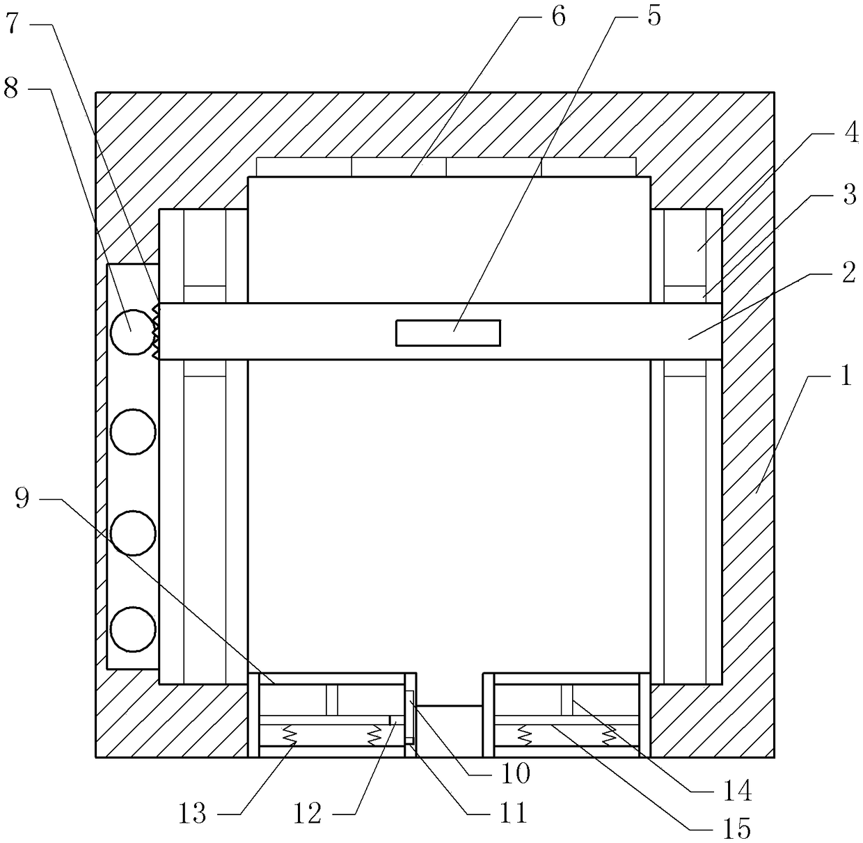
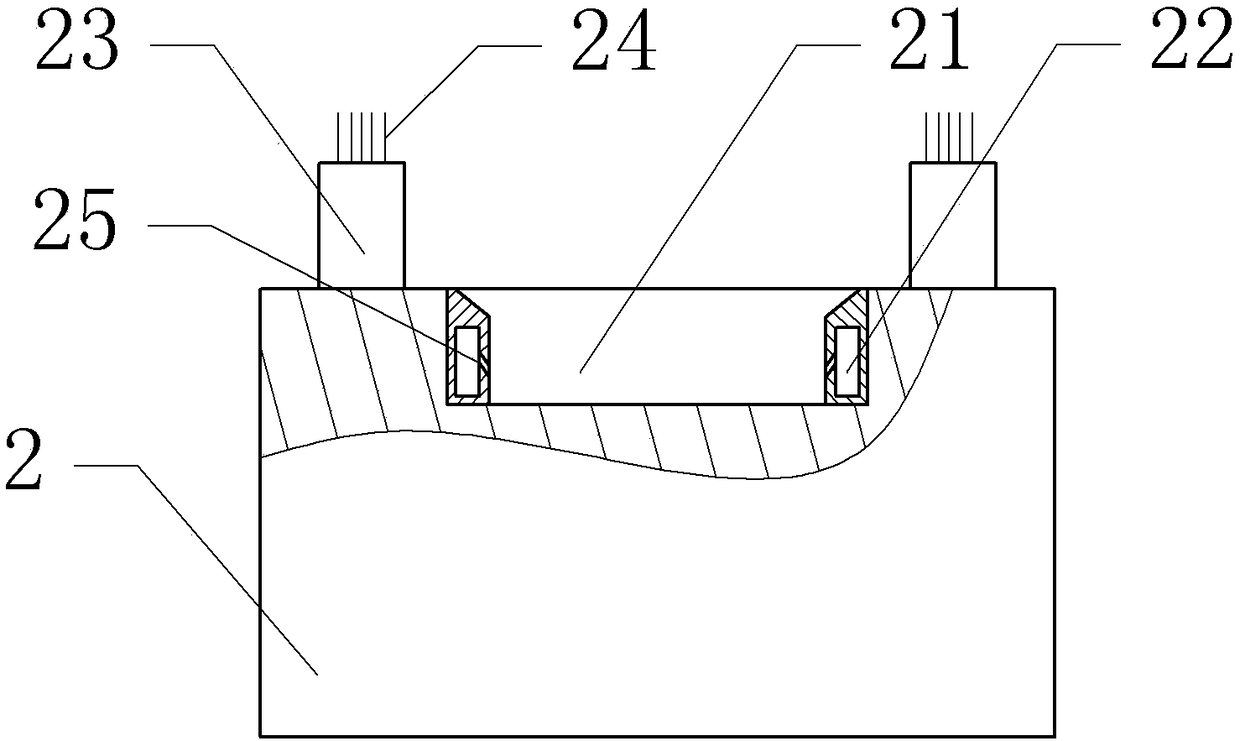
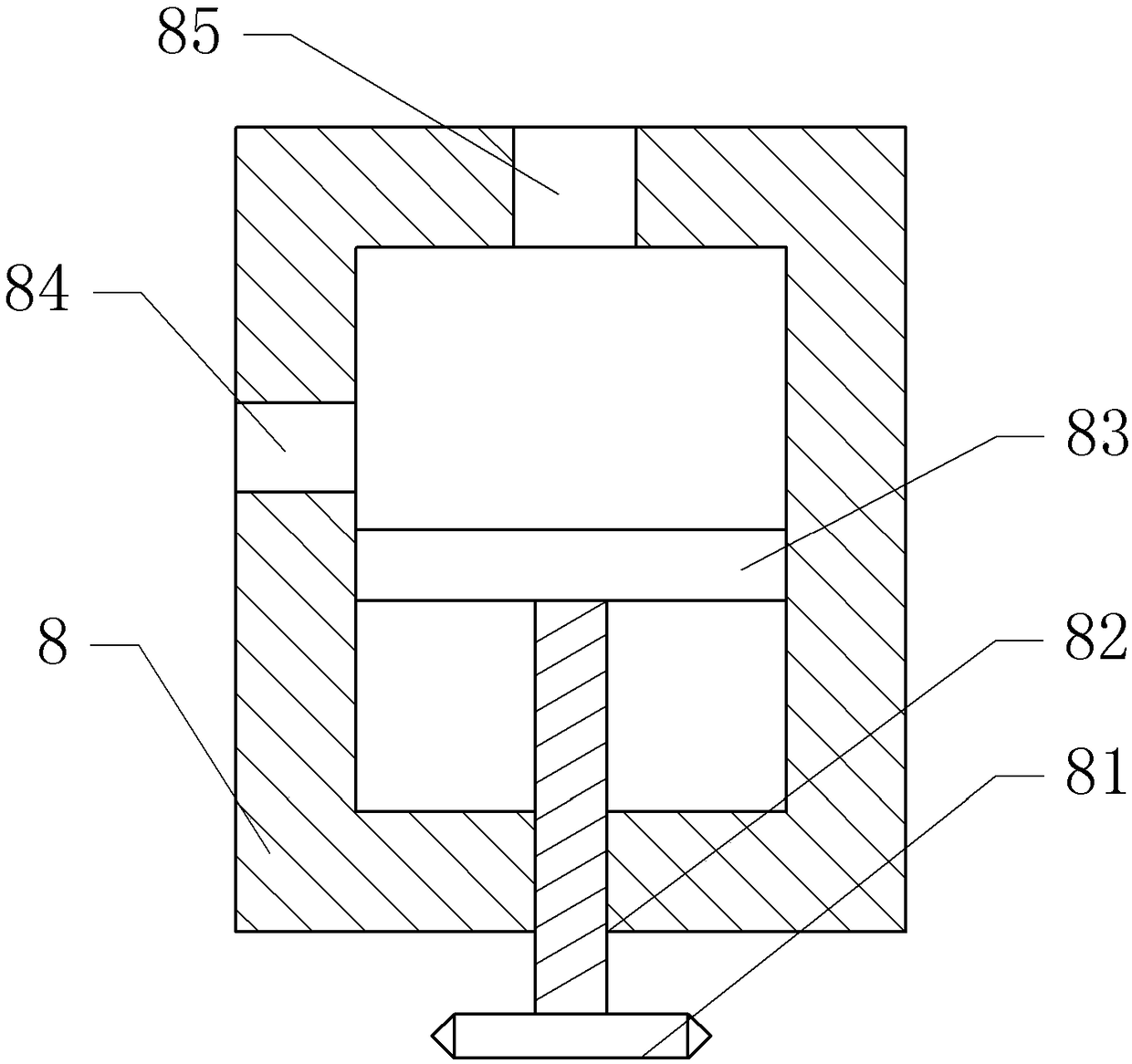
[0024] as attached figure 1 As shown, a dust removal and maintenance equipment for a computer room includes a frame and an electrostatic precipitator 2, four air nozzles 6 are arranged on the top of the frame, the air nozzles 6 are connected with a blower, and a pedal box is arranged at the bottom of the frame.

[0025] A pedal 9 and a slide plate 15 are slidably connected to the pedal box, the pedal 9 and the slide plate 15 can slide vertically on the pedal box, a push rod 14 is fixed between the pedal 9 and the slide plate 15, and a conductive part 12 is fixed on one side of the slide plate 15. The conductive part 12 is a copper sheet. The bottom of the slide plate 15 is provided with a spring 13, one end of the spring 13 is fixed on the slide plate 15, and the other end of the spring 13 is fixed on the pedal box. The side wall of the stepping box is fixed with conductive parts by fastening bolts, and the conductive parts include a conductive plate 10 and an insulating part...


PUM


Abstract

The invention relates to the technical field of equipment maintenance, and discloses a dedusting and maintaining device for a computer room. The dedusting and maintaining device for the computer roomcomprises a frame and an electrostatic dust collector, wherein multiple air injection nozzles are arranged on the top part of the frame and communicate with an air blower; a treading mechanism is arranged on the bottom part of the frame, and comprises treading tanks; a pedal and a sliding plate are arranged on each treading tank; a push rod is fixed between each pedal and each sliding plate; a conductive part is arranged on one side of each sliding plate; springs are arranged on the bottom part of each sliding plate; a conductive piece is arranged on a side wall of each treading tank and comprises an insulation part and a conductive plate; linear motor modules are arranged on two sides of the frame; a rack is arranged on one side of the electrostatic dust collector; an annular cavity is arranged on an air inlet of the electrostatic dust collector; air holes are formed in the annular cavity; air tanks are arranged on the frame; pressing plates are arranged in the air tanks; screw rods are fixedly connected onto the pressing plates; gears are fixed onto the screw rods; and air inlet one-way valves and air outlet one-way valves are arranged on the air tanks. The dedusting and maintaining device for the computer room provided by the invention is simple in structure, and capable of reducing the amount of powder dust entering the computer room, and plays a role in maintaining the computer room.

Description

technical field [0001] The invention relates to the technical field of equipment maintenance, in particular to a dust removal maintenance equipment for a computer room. Background technique [0002] Nowadays, with the rapid development of the Internet and the popularization of computers, many units and schools have computer rooms. And these computer rooms are frequently used. Due to the large flow of people in the computer room, people will frequently move between classes or during the use of computers, and all computers work at the same time within a limited time and space. The static electricity released by electronic equipment is easy to absorb dust in the air. Excessive accumulation of these dusts will cause poor cooling effect of the computer on the one hand, and cause the computer to crash on the other hand. The accumulation of dust for a long time can also easily cause hardware failure of the computer. [0003] The existing computer dust removal method is to regula...

Claims


Application Information

Patent Timeline
Patent Type & Authority Applications(China)
IPC IPC(8): B03C3/68B08B1/00B08B7/02F24F3/16
CPCB03C3/68B08B7/02F24F2120/20F24F8/192B08B1/12
Inventor 李小琼
Owner 重庆春信实业有限公司
Learn More