
An auxiliary tooling for dispersing and forming a gel fiber into a net

An auxiliary tooling, gel fiber technology, applied in fiber processing, filament/thread forming, textile and papermaking, etc., can solve the problems of difficult cleaning, failure in production, inconvenience in taking out the finished fiber web, etc., to improve the heat exchange rate and Air-drying speed, avoid air leakage, improve the effect of spinning quality

Active Publication Date: 2022-03-22
山东东珩国纤新材料有限公司
View PDF0 Cites 0 Cited by
  • Summary
  • Abstract
  • Description
  • Claims
  • Application Information

AI Technical Summary

Problems solved by technology

[0003] The existing gel fiber spinning device still needs to be improved as a whole. For example, one of the common problems in gel spinning is that the gel fiber thrown out is not dried in time, so that the fiber embryo body is prone to fiber adhesion. The obtained fiber effect is not ideal, and even the production fails, and the existing receiving tray is generally installed under the spinning tray in a fixed state, it is not easy to flexibly adjust its position, and it is also very inconvenient to take out the finished fiber web
[0004] Existing silk spinning discs generally do not have a mechanism for sealing the spinning hole in an emergency state. For example, during the spinning process, it is found that the spinning effect is not ideal, or the machine malfunctions. At this time, the spinning needs to be stopped. However, in the process of stopping, since the receiving plate does not stop instantly, it still has a certain speed to continue to throw the gel out along the spinning hole, which causes too much waste and even makes it difficult to clean. More troublesome consequences, so this needs to be improved

Method used


Image

  • An auxiliary tooling for dispersing and forming a gel fiber into a net
  • An auxiliary tooling for dispersing and forming a gel fiber into a net
  • An auxiliary tooling for dispersing and forming a gel fiber into a net

Examples


Embodiment Construction

[0034] The following will clearly and completely describe the technical solutions in the embodiments of the present invention with reference to the accompanying drawings in the embodiments of the present invention. Obviously, the described embodiments are only some, not all, embodiments of the present invention. Based on the embodiments of the present invention, all other embodiments obtained by persons of ordinary skill in the art without making creative efforts belong to the protection scope of the present invention.

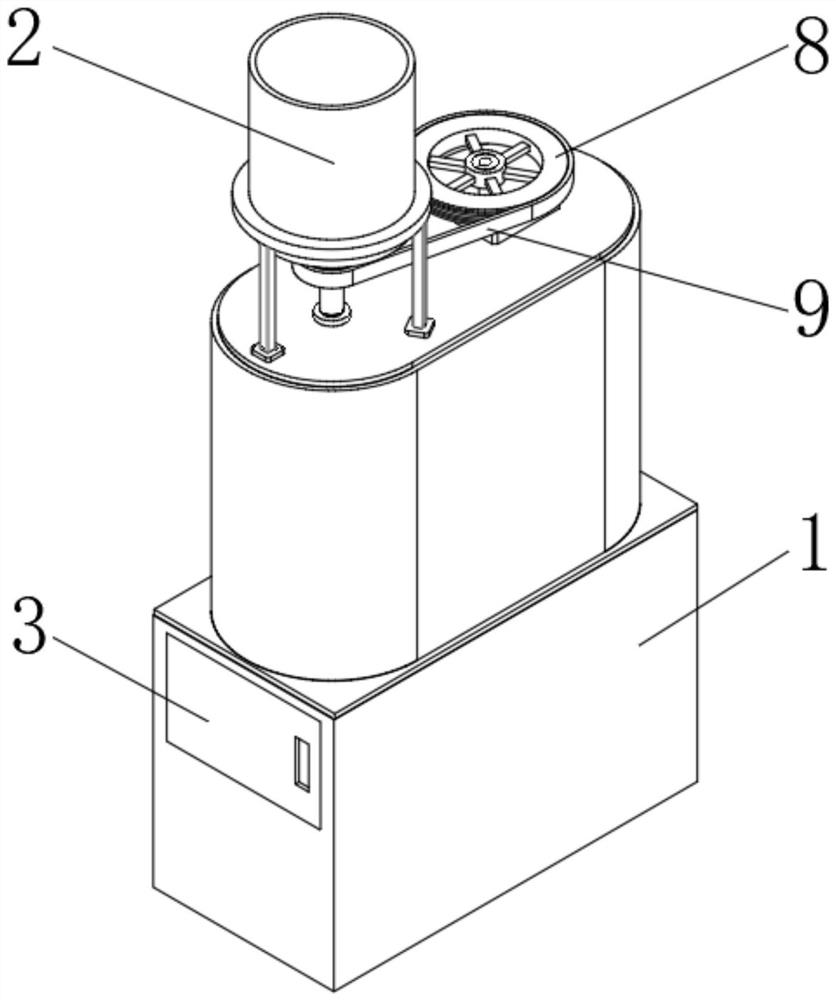
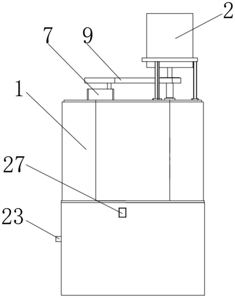
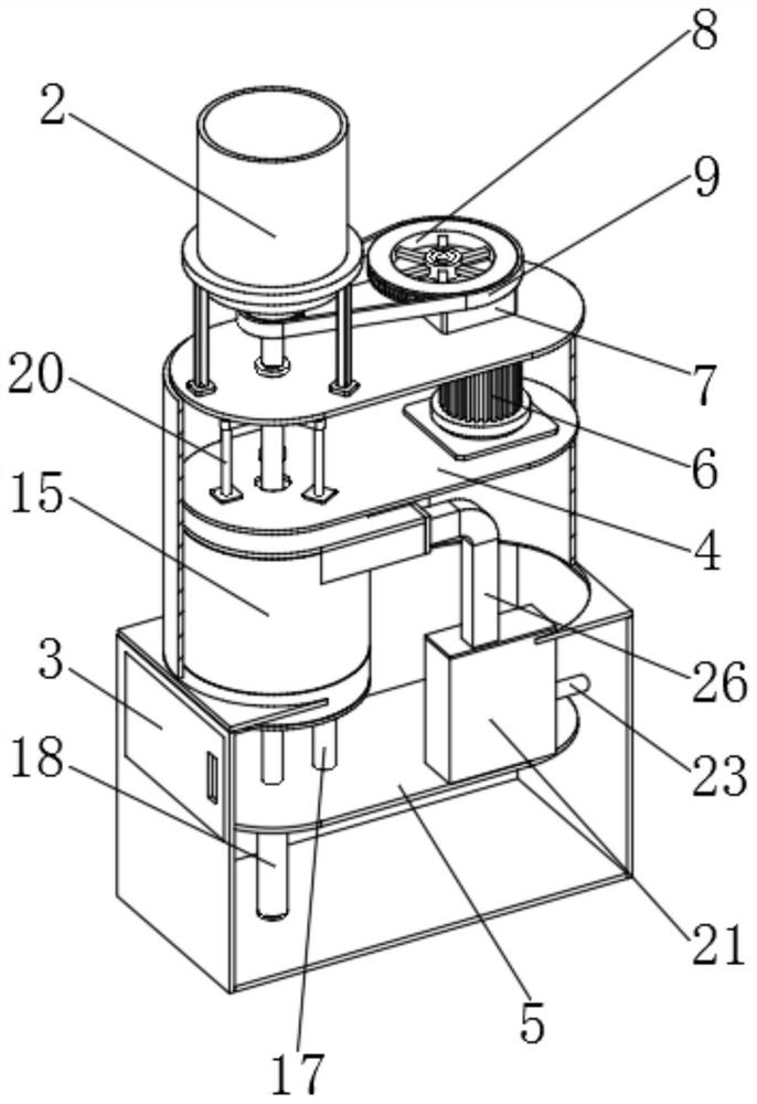
[0035] Such as Figure 1 to Figure 13 As shown, in the embodiment of the present invention, a kind of auxiliary tooling for dispersing gel fibers into a net, including a device housing 1, the top of the device housing 1 is fixedly equipped with a lower material barrel 2, and the device housing 1 is divided into an upper oval part and a lower rectangular part A side door 3 is fixedly installed on the left side of the lower rectangular part of the device shell 1...


PUM


Abstract

The invention belongs to the technical field of gel spinning, and discloses an auxiliary tooling for dispersing gel fibers into a net, including a device shell, the top of the device shell is fixedly equipped with a lowering barrel, and the device shell is divided into an upper oval part and the lower rectangular part, a side door is fixedly installed on the left side of the lower rectangular part of the device housing, and an upper partition and a lower partition are fixedly installed in the inner chambers of the upper oval part and the lower rectangular part of the lower bucket. The present invention heats the airflow through the heating box. After entering the outer enclosure from the air inlet channel, the airflow will flow along the connection tangent between the outer enclosure and the air inlet channel, and finally form a ring around the inside of the outer enclosure. Downward vortex, the annular cyclone airflow will fill the inner cavity of the entire outer enclosure, and its flow direction is opposite to the rotation direction of the spinner, which improves the heat exchange rate and air-drying speed of the gel fiber filaments, and prevents the fiber embryos from The body produces fiber adhesion and improves the quality of spinning.

Description

technical field [0001] The invention belongs to the technical field of gel spinning, in particular to an auxiliary tool for dispersing gel fibers into a net. Background technique [0002] Spinner refers to fiber-making equipment that spins molten or molten refractory raw materials into fibers by centrifugal force. There are two types of spinners: roller spinner and disc spinner. The former uses horizontal Shaft transmission is mainly used for fiber formation of molten aluminum silicate refractory fiber, and the latter is a vertical shaft transmission, which is mainly suitable for fiber formation of colloidal polycrystalline refractory fiber. [0003] The existing gel fiber spinning device still needs to be improved as a whole. For example, one of the common problems in gel spinning is that the gel fiber thrown out is not dried in time, so that the fiber embryo body is prone to fiber adhesion. The obtained fiber effect is not ideal, and even the production fails, and the exi...

Claims


Application Information

Patent Timeline
Patent Type & Authority Patents(China)
IPC IPC(8): D01D5/18D04H1/70D04H3/02
CPCD01D5/18D04H1/70D04H3/02
Inventor 朱东春范宗忠井良霄
Owner 山东东珩国纤新材料有限公司
Learn More