Cooling system of emergency cooling tank and nuclear power plant having the same

Active Publication Date: 2014-11-13
KOREA ATOMIC ENERGY RES INST
View PDF2 Cites 9 Cited by
  • Summary
  • Abstract
  • Description
  • Claims
  • Application Information

AI Technical Summary

Benefits of technology

[0030]In accordance with another exemplary embodiment disclosed herein, the opening and closing unit may prevent the emission of steam when a heat load transferred to the emergency cooling tank is reduce

Problems solved by technology

However, cooling water within the emergency cooling tank, to which the heat is transferred from the heat exchanger upon an occurrence of an accident, is gradually evaporated to be run out.
However, the air-cooling type heat exchanger exhibits lower cooling efficiency than the water-cooling type.
The heat transfer efficiency of transferring heat to the outside (to the air) through the wall surface of the tube is low.
Since the heat exchanger of the passive residual heat removal system is generally operating under high temperature and high pressure environments, design pressure thereof may be extremely high and economic feasibility is drastically lowered when the heat exchanger has an increased

Method used


Image

  • Cooling system of emergency cooling tank and nuclear power plant having the same
  • Cooling system of emergency cooling tank and nuclear power plant having the same
  • Cooling system of emergency cooling tank and nuclear power plant having the same

Examples


Example

[0049]Description will now be given in detail of the exemplary embodiments, with reference to the accompanying drawings. For the sake of brief description with reference to the drawings, the same or equivalent components will be provided with the same reference numbers, and description thereof will not be repeated. A singular representation may include a plural representation unless it represents a definitely different meaning from the context.

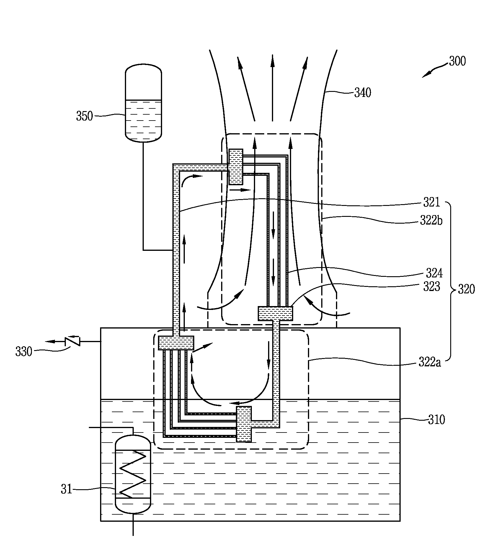
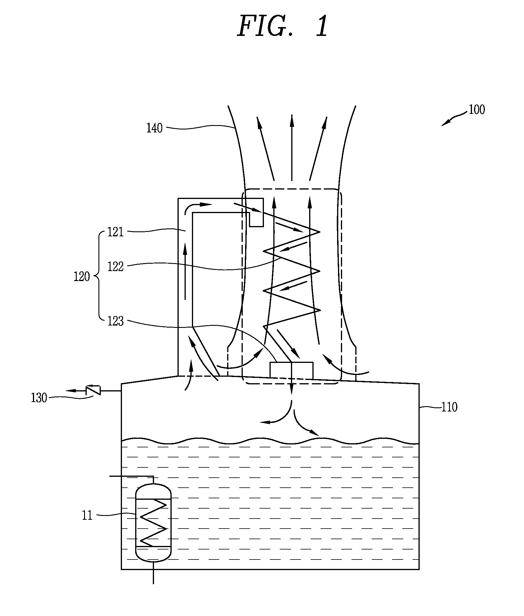
[0050]FIG. 1 is a conceptual view of a cooling system 100 of an emergency cooling tank (or an emergency cooling tank cooling system) in accordance with one exemplary embodiment disclosed herein.

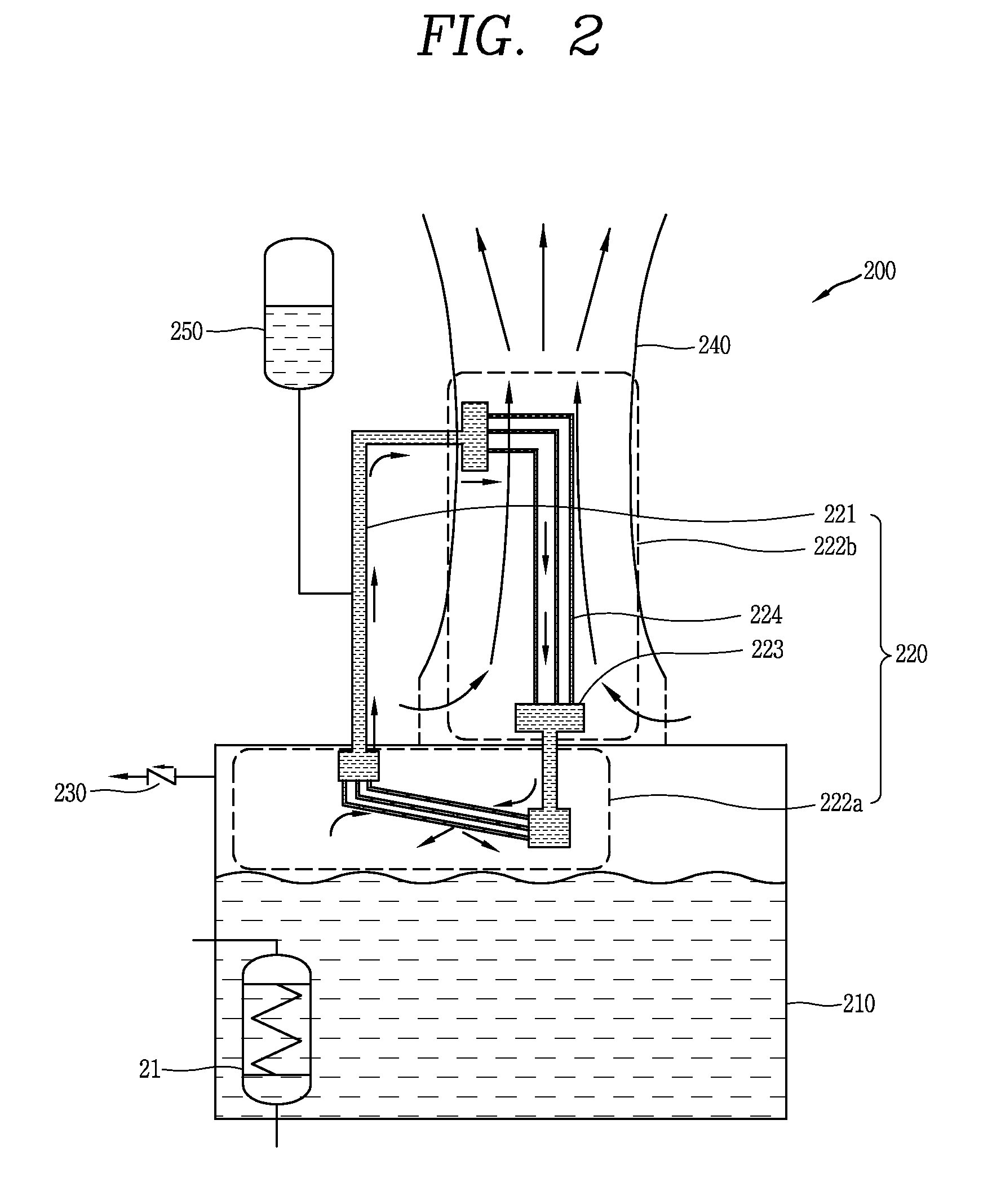
[0051]An emergency cooling tank cooling system 100 may be configured to externally emit heat transferred from a nuclear reactor or a containment, and include an emergency cooling tank 110, a heat exchanging device (or a cooling device) 120 and an opening and closing unit 130.

[0052]The emergency cooling tank 110 may be configured to store cooling water t...


PUM


Abstract

The present disclosure provides a cooling system of an emergency cooling tank, which enables long-term cooling without refilling cooling water, in case of the change in a quantity of heat transferred to the emergency cooling tank according to a lapse of time upon an occurrence of an accident of a nuclear reactor, and a nuclear power plant having the same. The emergency cooling tank cooling system includes an emergency cooling tank configured to store cooling water therein, the cooling water receiving heat, transferred from a nuclear reactor or a containment, when an accident occurs in the nuclear reactor, a heat exchanging device installed to be exposed to an outside of the emergency cooling tank to operate in air, and configured to externally emit heat by way of a heat exchange between fluid in the emergency cooling tank and the air such that the operation of the emergency cooling tank is continued even without refilling the cooling water, and an opening and closing unit installed at an upper portion of the emergency cooling tank to be located higher than a water level of the cooling water, and configured to be open by a flow of the fluid generated by an evaporation of the cooling water, the flow being formed due to a pressure difference from external air at pressure higher than a preset pressure, such that some of the fluid is externally emitted when a heat load exceeding a cooling capacity of the emergency cooling tank is transferred.

Description

CROSS-REFERENCE TO RELATED APPLICATION[0001]Pursuant to 35 U.S.C. §119(a), this application claims the benefit of earlier filing date and right of priority to Korean Application No. 10-2013-0052051, filed on May 8, 2013, the contents of which is incorporated by reference herein in its entirety.BACKGROUND OF THE DISCLOSURE[0002]1. Field of the Disclosure[0003]This specification relates to a cooling system of an emergency cooling tank with improved safety, which is capable of minimizing an increase in economical costs and maintaining a cooling function of the emergency cooling tank for a long term of time without refilling cooling water in the emergency cooling tank, by taking into account a characteristic of a quantity of heat transferred to the emergency cooling tank, as an ultimate heat sink, upon an occurrence of an accident of a nuclear reactor, and a nuclear power plant having the same.[0004]2. Background of the Disclosure[0005]An emergency cooling tank is used as a heat sink, w...

Claims


Application Information

Patent Timeline
IPC IPC(8): G21C15/18
CPCG21C15/18G21C13/02G21C15/12G21D3/06Y02E30/00Y02E30/30
Inventor KIM, YOUNG INKIM, KEUNG KOOBAE, YOUNG MINYOON, JU HYEONHA, JAE JOOLEE, WON JAEKIM, TAE WAN
Owner KOREA ATOMIC ENERGY RES INST
Why Eureka
Try Eureka