Tape cartridge

a technology of tape cartridges and brake locks, applied in the field of tape cartridges, can solve the problems of vibrations emitted by vibrations, and achieve the effect of stabilizing the brake lock member

Inactive Publication Date: 2008-04-29
TDK CORPARATION
View PDF3 Cites 0 Cited by
  • Summary
  • Abstract
  • Description
  • Claims
  • Application Information

AI Technical Summary

Benefits of technology

[0008]It is an object of the present invention to provide a tape cartridge capable of preventing emission of abnormal sounds and chipping of a tooth in a brake lock member and preventing emission of vibrating sounds and occurrence of abrasion at a usage time when a reel hub unit rotates at a high rotating speed because of being increased in capacity or at a producing time when the reel hub unit rotates at the high rotating speed for rewinding a tape-shaped recording medium.
[0010]According to the tape cartridge, the brake release member, which rotates together with the reel hub unit when used, is provided with the protruded portion taking the curved-surface shape or the circular conic shape, and the bearing portion of the non-rotating brake lock member has the flat surface. Hence, when the brake release member rotates, a tensile force acting from the center toward the outside is not applied to the brake lock member on the non-rotating side as the flat-surface like bearing portion contacts with the protruded portion, taking the curved-surface shape or the circular conic shape, of the brake release member. Therefore, even if the reel hub unit rotates at a high rotating speed when in use and in production, the brake lock member is kept stable with neither a shift nor a tilt. Hence, it is possible to prevent emission of the vibrating sounds and occurrence of abrasion in the brake lock member. It is also possible to prevent a contact between the engaging portion of the brake lock member and the engaged portion on the side of the reel hub unit and the emission of abnormal sounds and chipping when in use and in production.
[0013]According to the tape cartridge, the central axis of the bearing portion deviates from the rotating central axis of the brake release member, and hence a force acting to move toward the outside from the central axis of the bearing portion is applied to the brake lock member on the non-rotating side. On the other hand, there is the force acting to return with the biasing force by the biasing member, and consequently both of these forces are kept in balance. With this operation, even if the reel hub unit rotates at the high rotating speed when in use and in production, the brake lock member is kept stable with neither the shift nor the tilt. Hence, it is possible to prevent the contact between the engaging portion of the brake lock member and the engaged portion on the side of the reel hub unit and the emission of abnormal sounds and chipping when in use and in production. It is also possible to prevent the emission of the vibrating sounds and the occurrence of abrasion in the brake lock member.
[0015]Moreover, it is preferable that the protruded bearing portion has a curved surface portion provided about the central axis and contacting with the contact surface, and a radius of the curved-surface portion is set within the range of 10 mm through 30 mm. With this contrivance, it is feasible to restrain the tilt of the brake lock member through the built-in clearance between the case and the brake lock member. It is therefore possible to stabilize the brake lock member with the bearing portion. This contrivance also makes it possible to surely prevent the emission of the abnormal sounds and to surely prevent the emission of the vibrating sounds and the occurrence of the abrasion in the brake lock member.

Problems solved by technology

With this operation repeated, vibrations are caused to emit vibrating sounds.

Method used


Image

  • Tape cartridge
  • Tape cartridge
  • Tape cartridge

Examples


first embodiment

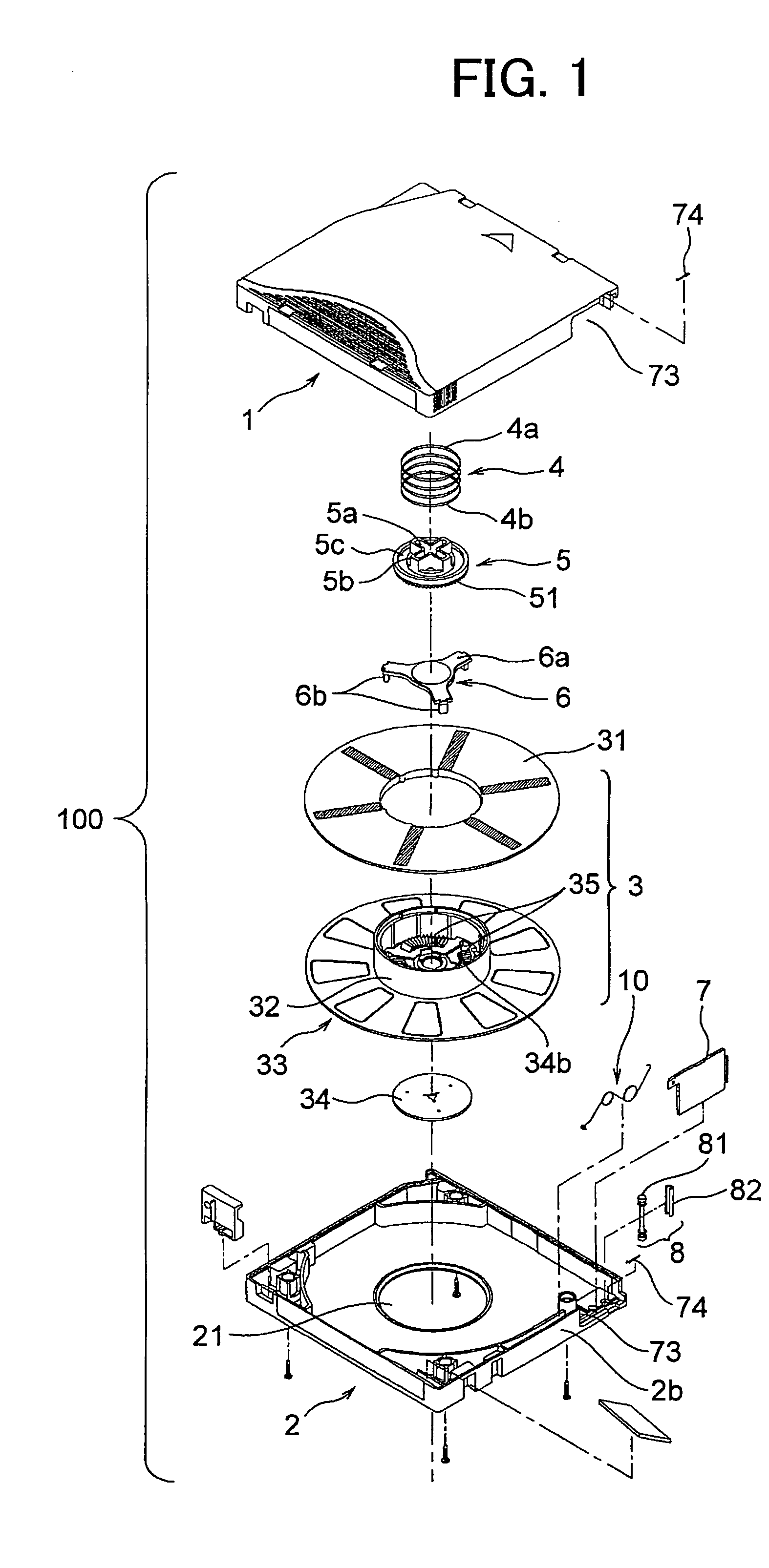
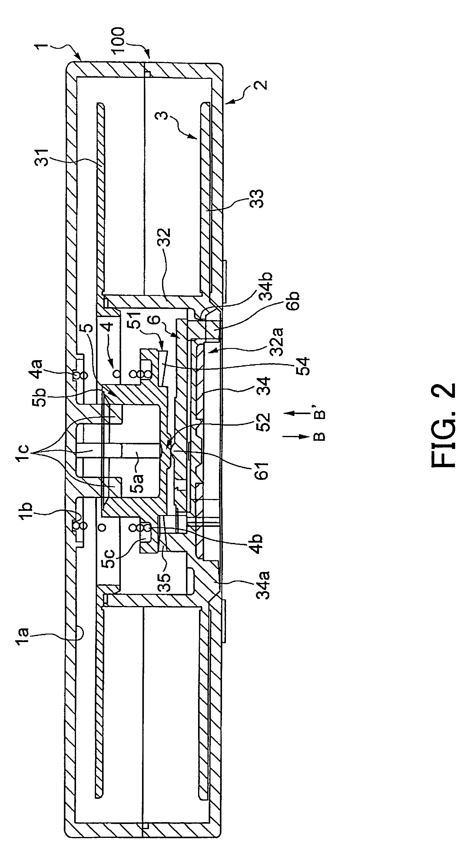
[0028]FIG. 1 is an exploded perspective view of a tape cartridge according to a first embodiment. FIG. 2 is a vertical sectional view showing a state where a reel hub unit is locked in the tape cartridge in FIG. 1. FIG. 3 is similarly a vertical sectional view showing a state where the reel hub unit is unlocked.

[0029]A tape cartridge 100 shown in FIG. 1 is constructed as a 1-reel type tape cartridge structured of an upper case 1 and a lower case 2. The tape cartridge 100 has a configuration that a reel hub unit 3 wounded with a magnetic recording tape (which will hereinafter simply be referred to as a [tape]) defined as a tape-shaped recording medium is provided inside and becomes rotatable when loaded into a recording / reproducing apparatus. The upper case 1 and the lower case 2 are assembled together to build up a flat case taking a rectangular or substantially square shape, and can be each made from a resinous material and manufactured by molding.

[0030]The reel hub unit 3 includes...

second embodiment

[0049]FIG. 6 is an exploded perspective view of the tape cartridge in a second embodiment. FIG. 7 is a vertical sectional view showing a state where the reel hub unit is locked in the tape cartridge in FIG. 6. FIG. 8 is similarly a vertical sectional view showing a state where the reel hub unit is unlocked.

[0050]As illustrated in FIGS. 6 through 8, the tape cartridge in the second embodiment has substantially the same configuration as FIGS. 2 and 3 show, except a construction of the bearing portion 52 of the brake lock member 5 and a construction of the brake release member 6 contacting with the bearing portion 52, and hence the explanations of the same components are omitted.

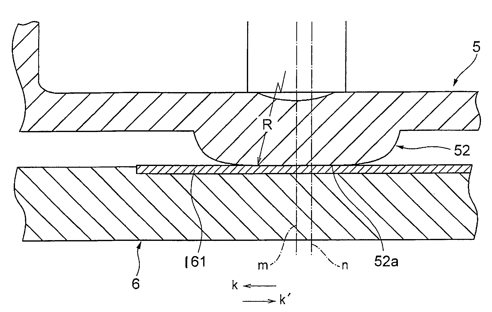
[0051]The bearing portion 52 of the brake lock member 5 in FIGS. 7 and 8 will be explained with reference to FIGS. 9 and 10. FIG. 9 is a principal vertical sectional view showing a contact portion between the bearing portion of the brake lock member and a butting plate of the brake release member in FIGS. 6 to ...

examples

[0065]Next, the second embodiment will be explained more specifically by way of examples. As in Table 1 that follows, the 1-reel type tape cartridge, as shown in FIG. 6, having a tape width of 12.65 mm is manufactured in a way that changes the offset quantity (n−m) to 0.1 mm, 0.2 mm, 0.3 mm, 0.5 mm, 1.0 mm and 1.5 mm by way of examples 1 through 6. Further, the radius R of the curved-surface portion 52a of the brake lock member 5 is changed such as 8 mm, 10 mm, 15 mm, 25 mm, 30 mm and 35 mm. Moreover, the same tape cartridge having none of the offset quantity is manufactured by way of a comparative example 1. Still further, the same tape cartridge having the offset quantity of 2 mm is manufactured by way of a comparative example 2. Yet further, the offset quantity is set to 0 mm through 1.5 mm, and the radius R of the curved-surface portion 52a of the brake lock member 5 is changed to 35 mm by way of a comparative example 3.

[0066]

TABLE 1ComparativeComparativeExamples 1 to 6Example 2...


PUM

PropertyMeasurementUnit
radiusaaaaaaaaaa
radiusaaaaaaaaaa
radiusaaaaaaaaaa

Abstract

A tape cartridge capable of preventing emission of vibrating sounds and occurrence of abrasion at a usage time when a reel hub unit rotates at a high rotating speed. The tape cartridge has a single reel hub unit rotatably accommodated in a case and having its periphery wound with a tape-shaped recording medium, a brake lock member including an engaging portion for engaging a reel hub unit to restrict rotation of the reel hub unit when in non-use, and a flat surface bearing portion provided substantially at a central part of the brake lock member, wherein the central axis of said flat surface bearing portion of the brake lock member is parallel with and offset from the rotating central axis around which said brake release member rotates together with said reel hub unit.

Description

BACKGROUND OF THE INVENTION[0001]1. Field of the Invention[0002]The present invention relates to a tape cartridge constructed to restrict a rotation of a reel hub by a brake lock member when in non-use and to release the reel hub from locking when in use.[0003]2. Description of the Prior Art[0004]A 1-reel type tape cartridge has a single reel hub unit inside, and a tape-shaped recording medium is wound along the periphery of the hub. This type of tape cartridge is employed for storing backup data for a computer, and so forth. When this type of tape cartridge is loaded into a magnetic recording / reproducing apparatus for the computer, the tape-shaped recording medium wound along the hub periphery of the reel hub unit is led out and then rewound on a reel hub unit on the side of the magnetic recording / reproducing apparatus. Then, the tape-shaped recording medium runs between the reel hub units on both sides, whereby recording and reproducing are conducted.[0005]In a conventional tape c...

Claims


Application Information

Patent Timeline
Patent Type & Authority Patents(United States)
IPC IPC(8): G11B23/107G11B23/04
CPCG11B23/043G11B23/107
Inventor SASAKI, MORIMASASATOH, TAKATERUKOUZU, CHOTARO
Owner TDK CORPARATION
Why Eureka
Try Eureka