Organic electroluminescence element

a technology of electroluminescence element and organic material, which is applied in the direction of discharge tube/lamp details, transportation and packaging, other domestic objects, etc., to achieve the effect of improving color purity and/or durability of the elemen

Active Publication Date: 2006-03-02
IDEMITSU KOSAN CO LTD
View PDF17 Cites 79 Cited by
  • Summary
  • Abstract
  • Description
  • Claims
  • Application Information

AI Technical Summary

Benefits of technology

[0030] In order to solve the problems, the present inventors have found out that in an organic EL element having at least two emitting layers, the light emission of the

Problems solved by technology

However, there is not known any organic EL element which has a multi-layered, laminated structure,

Method used


Image

  • Organic electroluminescence element
  • Organic electroluminescence element
  • Organic electroluminescence element

Examples


example 1

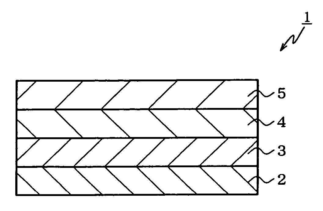
[0212] A glass substrate, 25 mm×75 mm×1.1 mm thick, having an ITO transparent electrode (manufactured by Geomatics Co.) was subjected to ultrasonic cleaning in isopropyl alcohol for 5 minutes followed by UV ozone cleaning for 30 minutes.

[0213] The washed glass substrate having the transparent electrode lines was set up on a substrate holder in a vacuum deposition device. First, an N,N′-bis(N,N′-diphenyl-4-aminophenyl)-N,N-diphenyl-4,4′-dia mino-1,1′-biphenyl film (abbreviated to the “TPD 232 film” hereinafter) was formed into a film in thickness of 60 nm on the surface on which the transparent electrode lines were formed, so as to cover the transparent electrode. This TPD 232 film functions as a hole injecting layer.

[0214] After the formation of the TPD 232 film, an N,N,N′,N′-tetra(4-biphenyl)-diaminobiphenylene layer (abbreviated to the “TBDB layer” hereinafter) having a film thickness of 20 nm was formed on the TPD 232 film. This film functions as a hole transporting layer.

[021...

example 2

[0220] An organic EL element was produced (a first dopant: about 3.3% by mol, and a second dopant: about 5.3% by mol) in the same manner as in Example 1 except that the film thickness of the first emitting layer was 10 nm, the ratio of D1 to H1 was 0.3:10 (ratio by weight), the film thickness of the second emitting layer was 30 nm, and the ratio of D2 to H1 was 1.4:30 (ratio by weight).

example 3

[0221] An organic EL element was produced (a first dopant: about 2.8% by mol, and a second dopant: about 5.7% by mol) in the same manner as in Example 1 except that the film thickness of the first emitting layer was 20 nm, the ratio of D1 to H1 was 0.5:20 (ratio by weight), the film thickness of the second emitting layer was 20 nm, and the ratio of D2 to H1 was 1.0:20 (ratio by weight).


PUM

PropertyMeasurementUnit
Thicknessaaaaaaaaaa
Energyaaaaaaaaaa
Energyaaaaaaaaaa

Abstract

An organic electroluminescence element comprising: an anode; a first emitting layer comprising at least a first host material and a first dopant; a second emitting layer comprising at least a second host material and a second dopant; and a cathode in the order mentioned: wherein the energy gap Egh1 of the first host material, the energy gap Egd1 of the first dopant, the energy gap Egh2 of the second host material, and the energy gap Egd2 of the second dopant satisfy the following formulas; and the luminescent intensity I1 at the maximum luminescent wavelength of an emission spectrum derived from the first emitting layer, and the luminescent intensity I2 at the maximum luminescent wavelength of an emission spectrum derived from the second emitting layer satisfy the following formula:
Egh1>Egd1
Egh2>Egd2
Egd1>Egd2
I1>3.5×I2.

Description

TECHNICAL FIELD [0001] The present invention relates to an organic electroluminescence element and, specifically, an organic electroluminescence element comprising an emitting layer having a bi-layered structure. BACKGROUND ART [0002] Electroluminescence elements, which uses electroluminescence (electroluminescence being abbreviated to “EL” hereinafter), have a high visibility because of spontaneous emission and further have good features, such as excellent impact resistance, because they are completely solid elements. Therefore, attention has been paid to the use thereof as light emitting elements in various display devices. [0003] The EL elements are classified into inorganic EL elements, wherein an inorganic compound is used for their luminescent material, and organic EL elements, wherein an organic compound is used therefor. In particular, the organic EL elements are being developed as next-generation light emitting elements since the elements enable to reduce the voltage to be ...

Claims


Application Information

Patent Timeline
IPC IPC(8): H01J1/88C09K11/06H05B33/12H01L51/00H01L51/30H01L51/50H05B33/14H05B33/20
CPCH01L51/005H01L51/0052H01L51/0054H01L51/0056H01L51/0058H01L51/0059Y10T428/24942H01L51/007H01L51/0081H01L51/5012H01L51/5036H01L51/5092Y10S428/917H01L51/006H10K85/60H10K85/615H10K85/622H10K85/624H10K85/631H10K85/626H10K85/633H10K85/6565H10K85/324H10K50/11H10K50/125H10K50/171C09K11/06H05B33/14
Inventor FUKUOKA, KENICHIMATSUURA, MASAHIDEYAMAMOTO, HIROSHIHOSOKAWA, CHISHIO
Owner IDEMITSU KOSAN CO LTD
Why Eureka
Try Eureka