Escape guiding apparatus and escape guiding system

a technology of escape guiding and guiding apparatus, which is applied in the field of escape guiding apparatus and escape guiding system, can solve the problems of increasing size, damage to the display part, and affecting visibility, and achieves the effect of high visibility

Inactive Publication Date: 2011-06-30
SEIKO EPSON CORP
View PDF5 Cites 79 Cited by
  • Summary
  • Abstract
  • Description
  • Claims
  • Application Information

AI Technical Summary

Benefits of technology

[0009]Since the image based on the escape guidance information is projected on the floor, even when, for example, an upper part of the space in a building is filled with smoke when a fire breaks out, the person who is escaping can see the escape guiding information projected on the floor. Moreover, since the apparatus adopts a system in which an image is projected on the floor by scanning the laser beam, the apparatus seldom produces an out-of-focus image which is sometimes produced by a normal projector. Furthermore, since the apparatus uses a laser beam with high color purity, the apparatus can instantly display an image guiding a person who is escaping, the image with higher visibility than that of an image produced by the normal projector. In addition, the apparatus can prevent a problem associated with a display part which is stained with dust or trodden by the shoes. As a result, it is possible to evacuate the person without delay when an emergency such as a disaster occurs.Application Example 2
[0013]According to the escape guiding apparatus described above, by changing the aspect ratio of the image to be projected with predetermined timing without changing the area of the image, it is possible to ensure the visibility of the image guiding a person who is escaping when an emergency such as a disaster occurs without changing the brightness of the image. This makes it possible to guide the escaping person for longer periods by making effective use of the battery even when power supply is stopped due to a power failure which occurs under emergency conditions.Application Example 4
[0023]According to the escape guiding apparatus described above, the moving direction determining section determines a moving direction of the person, and, when it is determined that the person is moving in a direction which is different from a direction in which the escaping person has to be guided, an image indicating that the person is moving in a wrong direction is projected. This makes it possible to guide the escaping person reliably when an emergency such as a disaster occurs.Application Example 9
[0028]Since in the escape guiding apparatus the image based on the escape guidance information is projected on the floor based on the evacuation order information from the server, even when, for example, an upper part of the space in a building is filled with smoke when a fire breaks out, the escaping person can see the escape guiding information projected on the floor. Moreover, since the apparatus adopts a system in which an image is projected on the floor by scanning the laser beam, the apparatus can instantly display an image with high visibility, the image guiding a person who is escaping. In addition, the apparatus can prevent a problem associated with a display part which is stained with dust or trodden by the shoes. As a result, it is possible to evacuate the person without delay when an emergency such as a disaster occurs.

Problems solved by technology

However, in the escape guiding apparatus described in Patent Document 1, since the display part is directly placed on the floor, the display part is damaged or stained by dust or by being trodden by the shoes.
This may impair visibility in an emergency.
Moreover, the escape guiding apparatus described in Patent Document 2 has to turn the projector and therefore increases in size.
In addition, a time lag etc. caused when the projector is turned delays escape guiding display at the time of disaster.
Moreover, since the apparatus adopts a system in which an image is projected on the floor by scanning the laser beam, the apparatus seldom produces an out-of-focus image which is sometimes produced by a normal projector.

Method used


Image

  • Escape guiding apparatus and escape guiding system
  • Escape guiding apparatus and escape guiding system
  • Escape guiding apparatus and escape guiding system

Examples


first embodiment

[0040]Hereinafter, an escape guiding apparatus according to a first embodiment will be described with reference to the drawings.

Schematic Configuration of Escape Guiding Apparatus

[0041]First, a schematic configuration of an escape guiding apparatus according to this embodiment will be described.

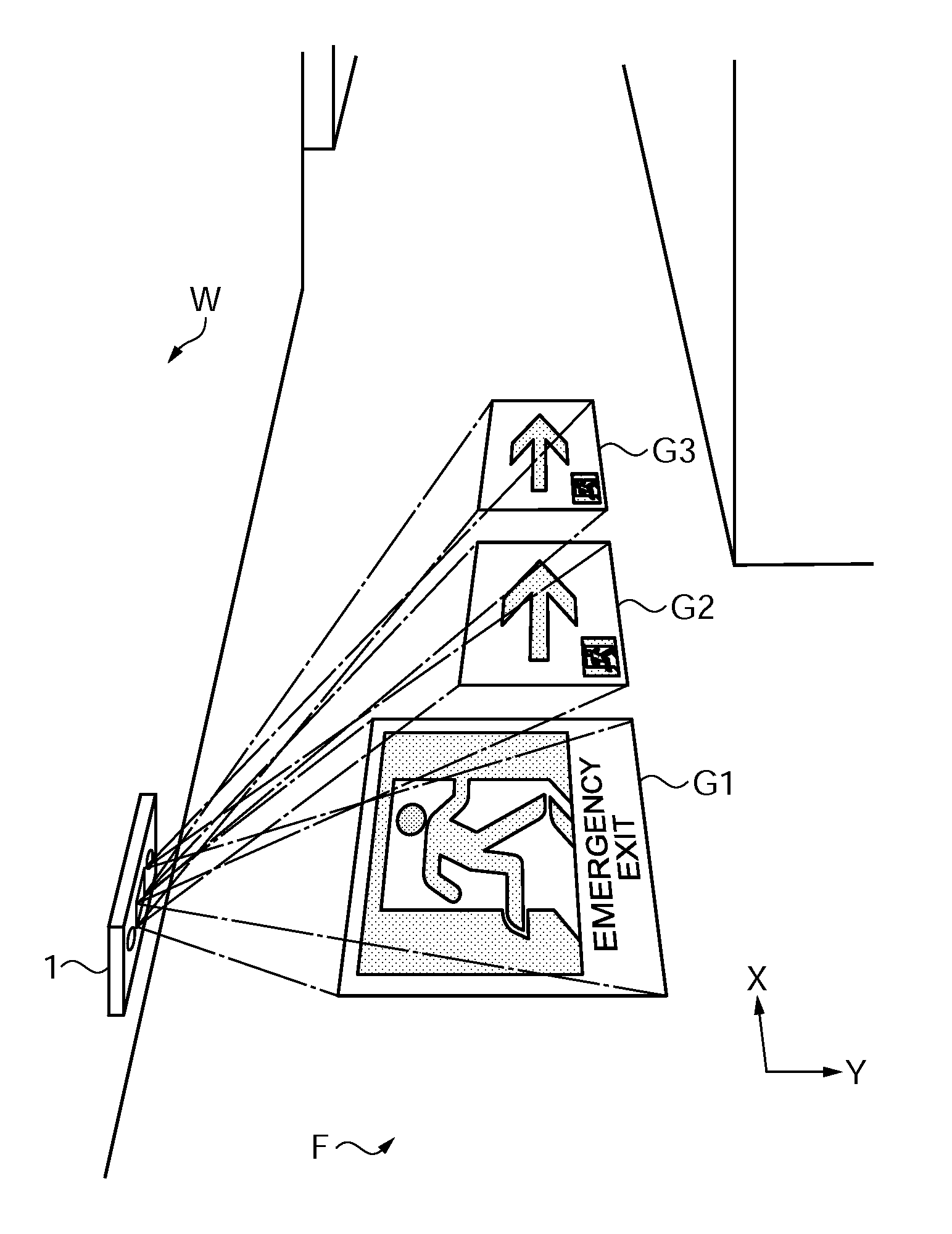
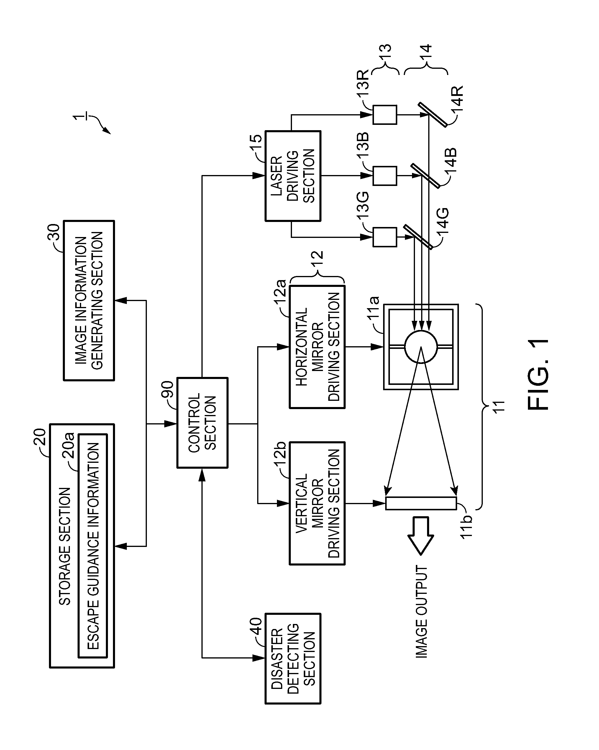
[0042]FIG. 1 is a block diagram showing a schematic configuration of an escape guiding apparatus 1 according to this embodiment. As shown in this drawing, the escape guiding apparatus 1 includes a light deflector 11, a driving section 12, a light source 13, a dichroic mirror 14, a laser driving section 15, a storage section 20, an image information generating section 30, a disaster detecting section 40, and a control section 90. Here, the light deflector 11, the driving section 12, the light source 13, the dichroic mirror 14, and the laser driving section 15 are configured as a projecting section projecting an image by scanning a laser beam.

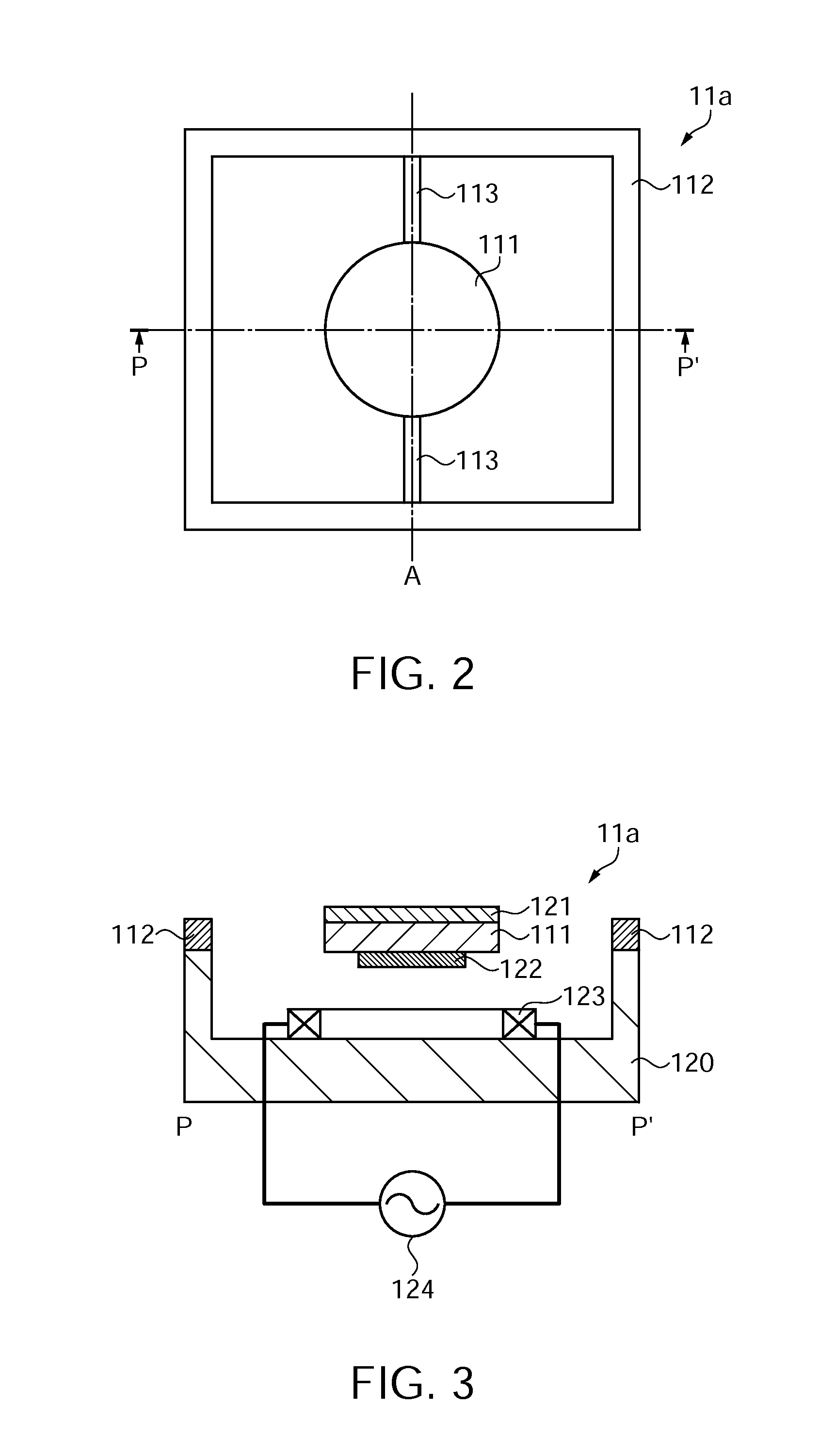
[0043]The light deflector 11 includes a horizontal m...

second embodiment

[0068]Hereinafter, an escape guiding apparatus according to a second embodiment will be described.

[0069]The escape guiding apparatus according to the second embodiment differs from the escape guiding apparatus according to the first embodiment described above in the function of the image information generating section 30 in the block diagram showing in the schematic configuration shown in FIG. 1. Incidentally, the escape guiding apparatus according to the second embodiment and the escape guiding apparatus according to the first embodiment are the same except for the image information generating section 30.

[0070]FIG. 6 is a flow chart showing the operation of the image information generating section 30 of the escape guiding apparatus according to the second embodiment. The flow chart of this drawing shows the operation for generating image information of an image to be projected on the floor of the passage based on the escape guidance information 20a obtained from the storage section...

third embodiment

[0082]Hereinafter, an escape guiding apparatus according to a third embodiment will be described.

[0083]The escape guiding apparatus according to the third embodiment differs from the escape guiding apparatus according to the first embodiment in the configuration of the block diagram showing the schematic configuration shown in FIG. 1.

[0084]FIG. 8 is a block diagram showing a schematic configuration of an escape guiding apparatus 2 according to the third embodiment. As shown in this drawing, the escape guiding apparatus 2 of this embodiment includes a moving direction determining section 70. Incidentally, the escape guiding apparatus 2 according to the third embodiment and the escape guiding apparatus according to the first embodiment are the same except for the moving direction determining section 70.

[0085]The moving direction determining section 70 is provided with a plurality of sensors including an infrared sensor and a human detection sensor which detect the presence of a person...


PUM


Abstract

An escape guiding apparatus includes: a projecting section projecting an image on a floor by scanning a laser beam; a storage section storing escape guidance information for guiding a person who is escaping; and an image information generating section generating image information of the image to be projected based on the escape guidance information stored in the storage section.

Description

BACKGROUND[0001]1. Technical Field[0002]The present invention relates to escape guiding apparatuses and escape guiding systems.[0003]2. Related Art[0004]In buildings and vehicles, a direction board guiding the people to the nearest emergency exit and a green-and-white guide light to the emergency exit are placed in order to evacuate the people immediately in the event of an emergency such as a disaster. In addition to the direction board and the guide light to the emergency exit, as an apparatus for guiding the people who are escaping, JP-A-2006-215703 (Patent Document 1), for example, proposes an escape guiding apparatus which places a guide light used at the time of evacuation on the floor or the treads of a stair. Moreover, JP-A-2004-329390 (Patent Document 2) proposes an escape guiding apparatus which projects and displays an image for guiding the people who are escaping by turning a projector.[0005]However, in the escape guiding apparatus described in Patent Document 1, since t...

Claims


Application Information

Patent Timeline
Patent Type & Authority Applications(United States)
IPC IPC(8): H04N9/31G03B21/00
CPCG08B7/062G08B7/066H04N9/3194H04N9/3188H04N9/3129
Inventor MURATA, AKIHIROKOBAYASHI, OSAMUHOSOMI, HIROAKI
Owner SEIKO EPSON CORP
Why Eureka
Try Eureka