
Display device

a display device and display section technology, applied in the field of display devices, can solve the problems of serious problems, ambient light may affect the display section of the display device, etc., and achieve the effects of enhancing the color purity of light, resisting deterioration, and low cos

Active Publication Date: 2008-01-22
MURAKAMI CORP +1
View PDF8 Cites 82 Cited by
  • Summary
  • Abstract
  • Description
  • Claims
  • Application Information

AI Technical Summary

Benefits of technology

The solution enhances color purity and resistance to ambient light-induced deterioration, providing clear image projection while maintaining a low cost structure, suitable for head-up displays and other applications.

Problems solved by technology

However, the display section of the display devices may be affected by ambient light.
To give an example, when an infrared ray or visible light contained in ambient light is irradiated on a display section, it may deteriorate because of heat generated by the irradiated light.
This becomes a serious problem.

Method used


Image

  • Display device
  • Display device
  • Display device

Examples


example

[0047]Concrete examples of the present invention will be shown below.

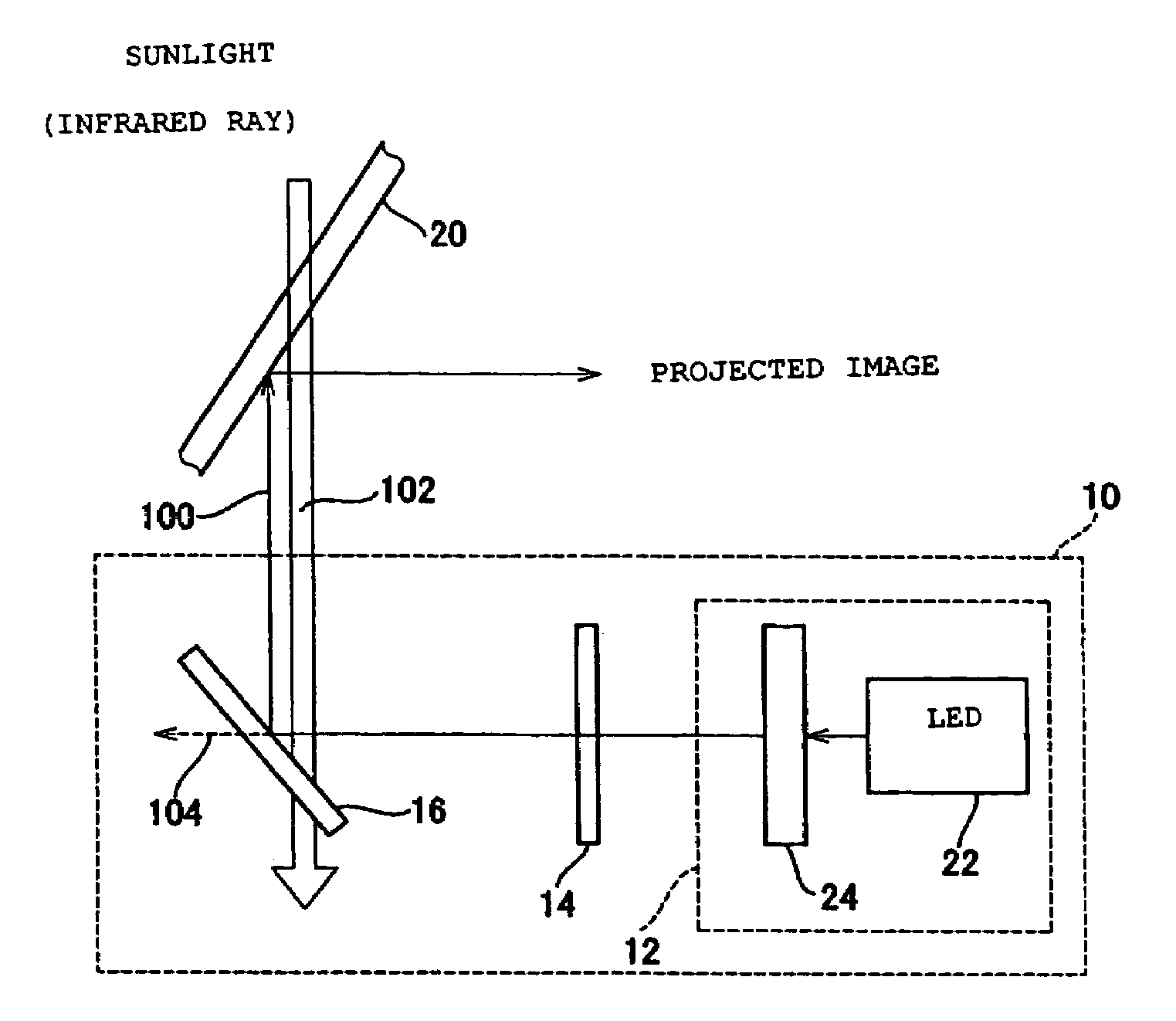
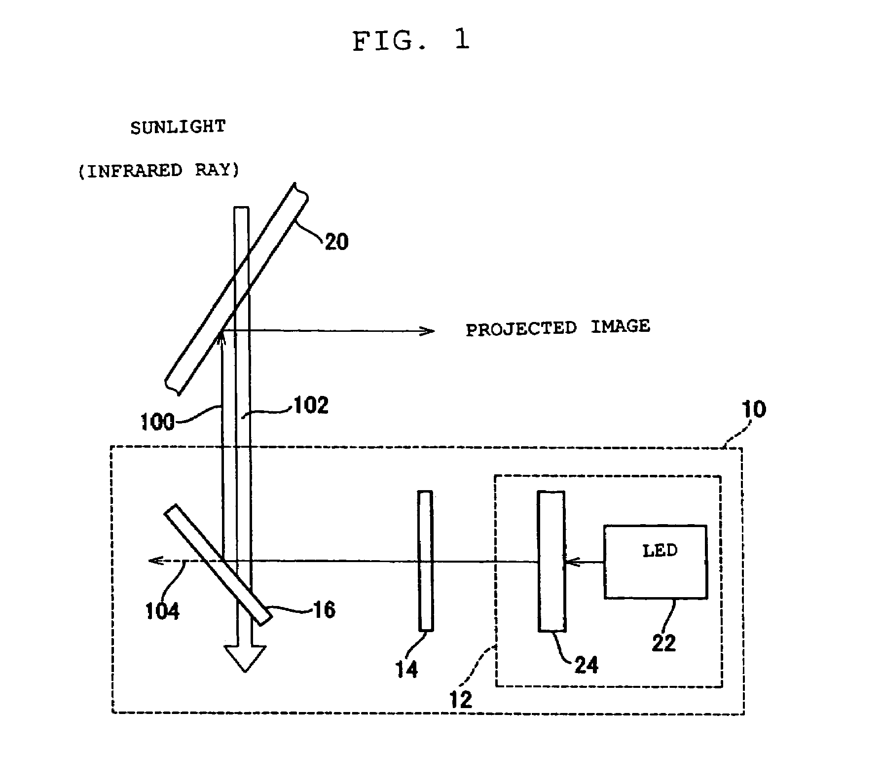
[0048]In the arrangement shown in FIG. 1, an LED for emitting burnt orange monochromatic light was used as the LED 22. Its peak wavelength was 612 nm and the FWHM was 50 nm. The filter 14 was positioned such that light from the display section 12 was incident to the filter 14 at 0°, and the mirror 16 was positioned such that light from the filter 14 was incident to the mirror 16 at 42.1°.

[0049]Note that the angles of the filter 14 and the mirror 16 are allowed to differ from the above angles, respectively. In this case, assume that the incident angles of the filter 14 and the mirror 16 are denoted by a° and b° in this order, they need to be arranged such that a relationship |a−b|≠0 is satisfied.

[0050]

TABLE 1DESIGN WAVELENGTH: 510 nmINCIDENT LIGHT ANGLE: 0 degreeH (TiO2): 2.3723L (SiO2): 1.4565LAYER NUMBERMATERIALOPTICAL THICKNESSSUBSTRATEGLASS0.1741H0.1602L0.2263H0.2464L0.1905H0.1506L0.2107H0.2108L0.2109H0.21010L0....


PUM


Abstract

Disclosed is a display device at a low cost which enhances the color purity of light to be projected, and which resists deterioration due to ambient light such as infrared ray. This display device includes an LED, an optical member for selectively outputting light components, of which wavelength is a predetermined minimum-limit wavelength or longer, from incident light, and a mirror for selectively reflecting light components, of which wavelength is a predetermined maximum-limit wavelength or shorter, from irradiated light. One of the optical member or the mirror receives light directly from the LED, and outputs it to the other. Subsequently, the other receives the light from one of the optical member and the mirror, and outputs it.

Description

BACKGROUND OF THE INVENTION[0001]1. Field of the Invention[0002]The present invention relates to a display device, more specifically to a display device that projects images on a windshield of a vehicle, or on any other surfaces.[0003]2. Cross Reference to Related[0004]The present application claims priority under 35 U.S.C. § 119 to Japanese Patent Application No. 2004-215746, filed on Jul. 23, 2004, entitled “DISPLAY DEVICE”. The contents of that application are incorporated herein by reference in their entirety.[0005]3. Description of the Related Art[0006]In a typical model of display devices for projecting images on a front window (i.e. windshield) of a vehicle, head up displays (HUDs) have been known. One example of HUDs is equipped with a dichroic mirror in order to efficiently project only colored light sent out from its display segment(s) or the like (refer to Utility Model Application Publication 64-35143). This dichroic mirror selectively reflects red light emitted from hea...

Claims


Application Information

Patent Timeline
Patent Type & Authority Patents(United States)
IPC IPC(8): F21V9/10G02B27/14F21V9/40
CPCG02B5/26G02B27/0101
Inventor SUGIKAWA, TOMOHIKONAGANO, KEIICHITAKAHASHI, YUICHIYOKOO, TERUKO
Owner MURAKAMI CORP
Learn More