
Non-sooting containerized candle

Inactive Publication Date: 2008-12-25
SC JOHNSON & SON INC
View PDF22 Cites 10 Cited by
  • Summary
  • Abstract
  • Description
  • Claims
  • Application Information

AI Technical Summary

Benefits of technology

[0018]The present invention relates to a non-sooting containerized candle. More particularly, the invention relates to an open-topped candle container having a pattern of holes in the upper wall portion of the container for venting the container so as to control air flow into and out of the container to provide complete combustion of the candle in the container and prevent emission of carbon particulates, commonly known as soot. A good burning candle, whether scented or unscented, is provided when fuel consumption is controlled and combustion is complete. When combustion is not complete, carbon particulates, along with water and carbon dioxide, which are the products of complete combustion, are also generated or emitted and deposited on the container wall and / or on a surface in the surrounding environment.
[0019]The pattern of holes in a container of the invention may be varied and are such so as to provide venting of the candle containers by controlling or adjusting air flow from a turbulent air flow to a laminar air flow while the candle is burning. Laminar air flow prevents the candle flame from flickering which in turn results in complete combustion and a clean or non-sooting burning candle. More particularly, laminar air flow occurs when a fluid flows in parallel layers, with no disruption between the layers. Laminar air flow is a flow regime characterized by high momentum diffusion, low momentum convection and pressure and velocity independent from time. Accordingly, laminar air flow is “smooth”, which is the opposite of turbulent air flow which is “rough”. Particularly, turbulent air flow is a flow regime characterized by chaotic, stochastic property changes. This includes low momentum diffusion, high momentum convection and rapid variation of pressure and velocity in space and time.

Problems solved by technology

However, many types of candles are not able to be properly controlled during burning thereof and, thus, do not provide complete combustion.

Method used


Image

  • Non-sooting containerized candle
  • Non-sooting containerized candle
  • Non-sooting containerized candle

Examples


Embodiment Construction

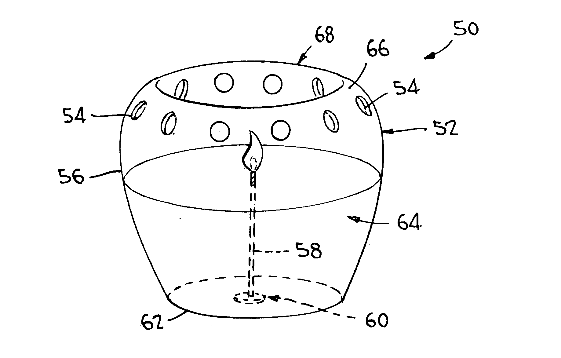
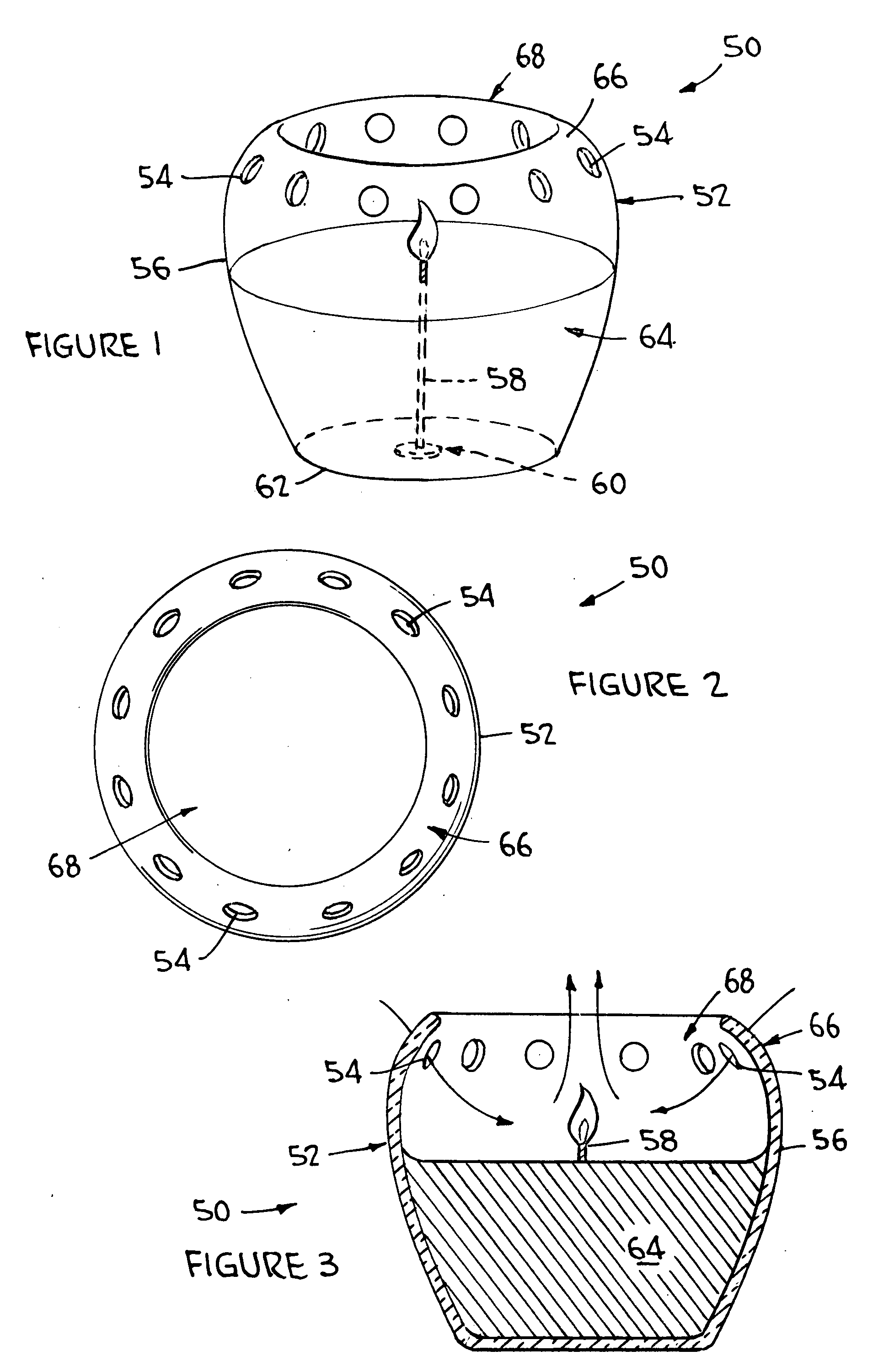
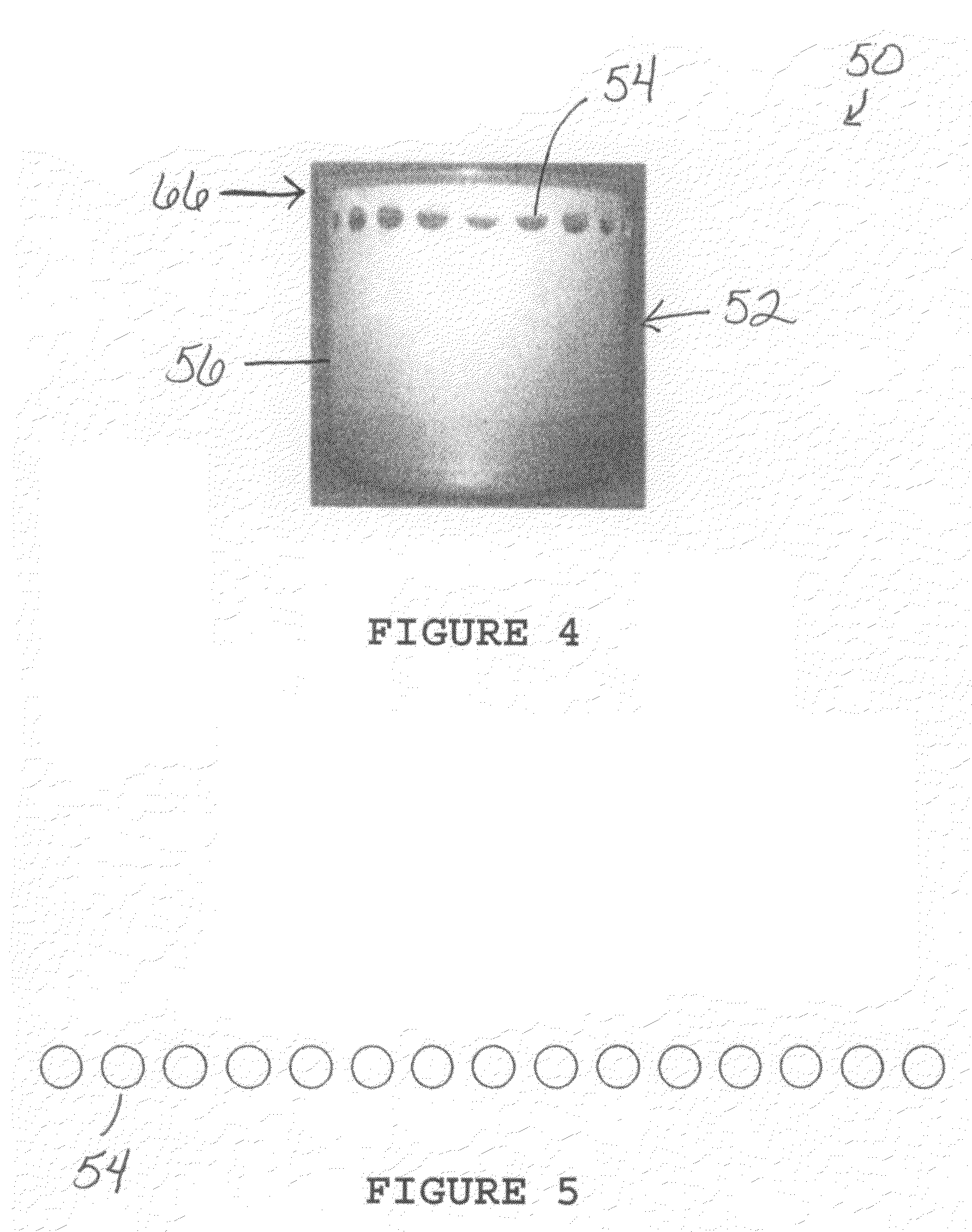
[0055]Referring to FIGS. 1-27, the present invention relates to a non-sooting containerized candle 50. More particularly, the invention relates to candle containers 52 having a pattern of holes 54 in the upper side wall portion 56 of the container 52 for venting the container to provide complete combustion of the candle in the container and to prevent emission of carbon particulates. A clean or non-sooting candle, whether scented or unscented, has controlled fuel consumption and complete combustion. When combustion is not complete, carbon particulates, along with water and carbon dioxide, which are the products of complete combustion, are also generated or emitted and deposited as soot on the container wall and / or a surface in the surrounding environment. This generally is an undesirable result of burning a candle for users. The containerized candle of the present invention reduces soot emission and, as such, is a non-sooting candle.

[0056]The containerized candle 50 of the present i...


PUM


Abstract

A non-sooting containerized candle is disclosed. The containerized candle includes a container having a top opening and a plurality of holes in an upper side wall portion of the container, a wick, a sustainer for securing the wick to the base of the container, and wax or other fuel material surrounding a major portion of the wick. The plurality of holes can be present in varying patterns in the upper side wall portion of the container to control air flow into and out of the container to provide complete combustion of the candle and prevent emission of carbon particulates. The pattern of holes control or adjust air flow around the burning wick from a turbulent air flow to a laminar air flow.

Description

FIELD OF INVENTION[0001]The present invention relates to a non-sooting containerized candle. More particularly, the invention relates to a candle container having a pattern of holes in the upper wall portion of the container for venting the container so as to control air flow into and out of the container to provide complete combustion of the candle in the container and prevent sooting or the emission of carbon particulates.BACKGROUND OF INVENTION[0002]Various types of candles are known. However, many types of candles are not able to be properly controlled during burning thereof and, thus, do not provide complete combustion. These candles may be burned by using a wick and / or in combination with a fuel. The products of complete combustion are water and carbon dioxide. When combustion is not complete, carbon particulates are also generated or emitted and deposited on a wall of a container for the candle or on a surface of the surrounding environment. These carbon particulates are comm...

Claims


Application Information

Patent Timeline
IPC IPC(8): F23D3/16
CPCA61L9/03C11C5/008F21S13/00F21V35/00F21V37/00F23D3/16F23D3/22F23D2700/001F23D2900/31
Inventor REQUEJO, LUZ P.PARKER, DEBORAH HOLMES
Owner SC JOHNSON & SON INC
Learn More