Inspection jig for radio frequency device ,and contact probe imcorporated in the jig

A fixture and probe technology, applied in the field of contact probes, can solve the problems of low durability, high cost and poor reliability of contact probes

Inactive Publication Date: 2004-06-09
YOKOWO CO LTD
View PDF1 Cites 16 Cited by
  • Summary
  • Abstract
  • Description
  • Claims
  • Application Information

AI Technical Summary

Problems solved by technology

In order to narrow the contact probe with complex structure, there are problems such as extremely high cost required, low durability and poor reliability of the contact probe

Method used


Image

  • Inspection jig for radio frequency device ,and contact probe imcorporated in the jig
  • Inspection jig for radio frequency device ,and contact probe imcorporated in the jig
  • Inspection jig for radio frequency device ,and contact probe imcorporated in the jig

Examples


Embodiment Construction

[0038] Specific embodiments of the present invention will be described in detail below with reference to the accompanying drawings.

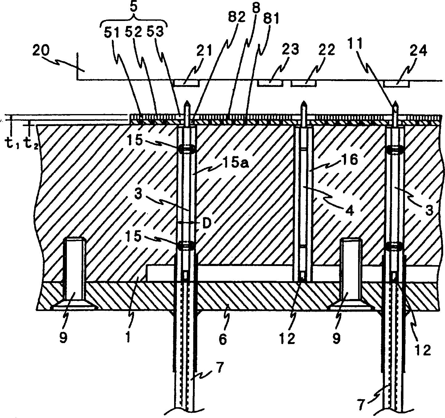
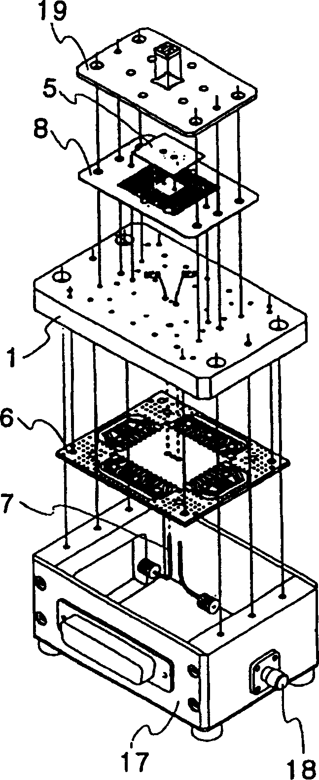
[0039] As shown in FIG. 1 , in the RF device inspection jig according to one embodiment of the present invention, an RF signal contact probe 3 is set in the metal block 1 , so that the tip of the retractable striker 11 protrudes from one side of the metal block 1 . The device under test 20 on which the RF circuit is formed is pressed against the metal block 1 so that the RF signal terminal 21 and the device under test terminal 24 are brought into contact with the contact probe 3 . By testing the test circuit in which the coaxial cable 7 is connected to the other end of the contact probe 3, the electrical test of the device 20 under test is performed.

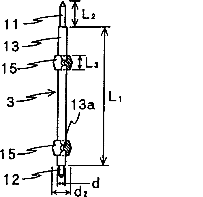
[0040]In this embodiment, the dielectric ring 15 is fixed at least two places on the periphery of the contact probe 3 and fitted into the through hole of the metal block 1 to form a hollow portion...


PUM


Abstract

In a jig for inspecting a device provided with at least a radio frequency signal terminal and an earth terminal, a metal block is formed with a through hole extending in a first direction. A contact probe is inserted into the through hole. The contact probe is provided with a metal pipe extending in the first direction. A plunger is retractably projected from one longitudinal end of the metal pipe to be brought into contact with the radio frequency signal terminal. At least two dielectric ring members are provided on an outer periphery of the metal pipe, and fitted with the through hole while forming a gap between the outer periphery of the metal pipe and an inner wall of the through hole, in order to form a coaxial path in which the contact probe serves as a core conductor and the metal block serves as an external conductor. A diameter of the through hole and a diameter of the dielectric ring members are selected such that the coaxial path has a predetermined impedance relative to the radio signal frequency terminal.

Description

technical field [0001] The present invention relates to an inspection jig and a contact probe incorporated in the jig for securely connecting inspection equipment to the device when inspecting the electrical characteristics of the device before it is mounted on a circuit board. The device under test corresponds to a module or IC (Integrated Circuit) of a high-frequency / high-speed circuit, such as an amplifier circuit, a mixer circuit, and a filter circuit incorporated in a cellular phone. Background technique [0002] In this specification, the above-mentioned high-frequency circuit is defined as an analog circuit that can work in the high-frequency range, and the above-mentioned high-speed circuit is defined as a digital circuit with extremely short pulse width and pulse interval of digital signals, and the analog high-frequency circuit and digital High-speed circuits are all referred to as RF (Radio Frequency) circuits or devices. The RF sign...

Claims


Application Information

Patent Timeline
Patent Type & Authority Applications(China)
IPC IPC(8): G01R31/26G01R1/06G01R1/067G01R1/073G01R31/28
CPCG01R1/07371G01R1/067
Inventor 佐藤温铃木光广铃木久史
Owner YOKOWO CO LTD
Why Eureka
Try Eureka