
Inspecting method and storage medium for storing program of the method

a technology of probe apparatus and program, which is applied in the direction of individual semiconductor device testing, semiconductor/solid-state device testing/measurement, instruments, etc., can solve the problems of large temperature difference between the target object and the probe, damage to the probe or the target object, and the reliability of inspection may deteriorate, so as to achieve the effect of increasing the operating rate of the probe apparatus and high reliability of inspection

Active Publication Date: 2009-01-01
TOKYO ELECTRON LTD
View PDF5 Cites 6 Cited by
  • Summary
  • Abstract
  • Description
  • Claims
  • Application Information

AI Technical Summary

Benefits of technology

[0011]In view of the above, the present invention provides an inspecting method capable of increasing an operating efficiency of a probe apparatus by performing inspection without heating or cooling a probe card in advance and also capable of performing highly reliable inspection by preventing misalignment between a target object to be inspected and probes and damages to the probe card or the target object, and a storage medium for storing a program of the method.
[0025]In accordance with the present invention, there can be provided an inspecting method capable of increasing an operating rate of a probe apparatus by performing inspection without heating or cooling a probe card in advance and also capable of performing highly reliable inspection by preventing misalignment between a target object to be inspected and probes and damages to the probe card or the object to be processed, and a storage medium for storing a program of the method.

Problems solved by technology

Therefore, a large temperature difference exists between the target object and the probes.
In that state, if the target object is overdriven by a normal overdrive amount, a probe pressure from the probes excessively increases to thereby inflict damages on the probes or the target object.
As a result, the reliability of the inspection may deteriorate.
However, the probes are extended in a horizontal direction as well as in a height direction, and it is difficult to solve the misalignment in the horizontal direction between the probes and the target object.
Besides, depending on types of probe cards, the probes do not properly contact with the electrode pads of the target object, whereby the reliability of the inspection may deteriorate.
These drawbacks occur in a low-temperature inspection as well as in a high-temperature inspection.

Method used


Image

  • Inspecting method and storage medium for storing program of the method
  • Inspecting method and storage medium for storing program of the method
  • Inspecting method and storage medium for storing program of the method

Examples


Embodiment Construction

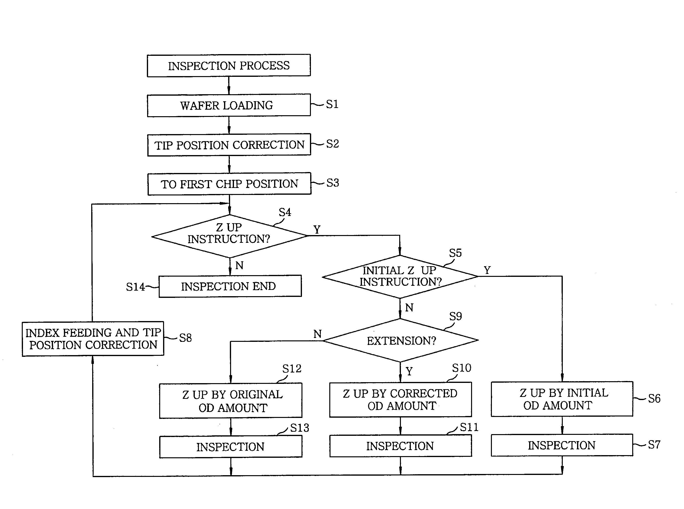
[0032]Embodiments of the present invention will be described with reference to FIGS. 1 to 5 which form a part hereof.

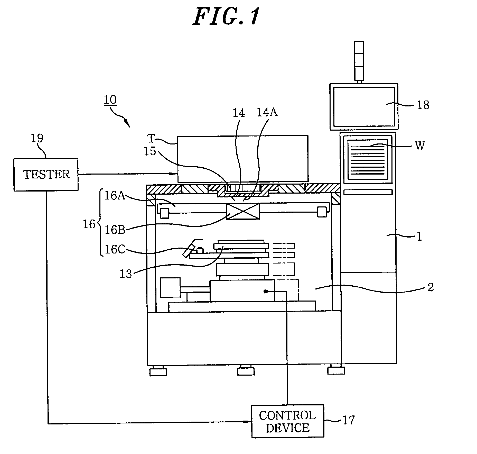
[0033]Hereinafter, a probe apparatus to which an inspecting method of this embodiment is applied will be explained with reference to FIGS. 1 and 2.

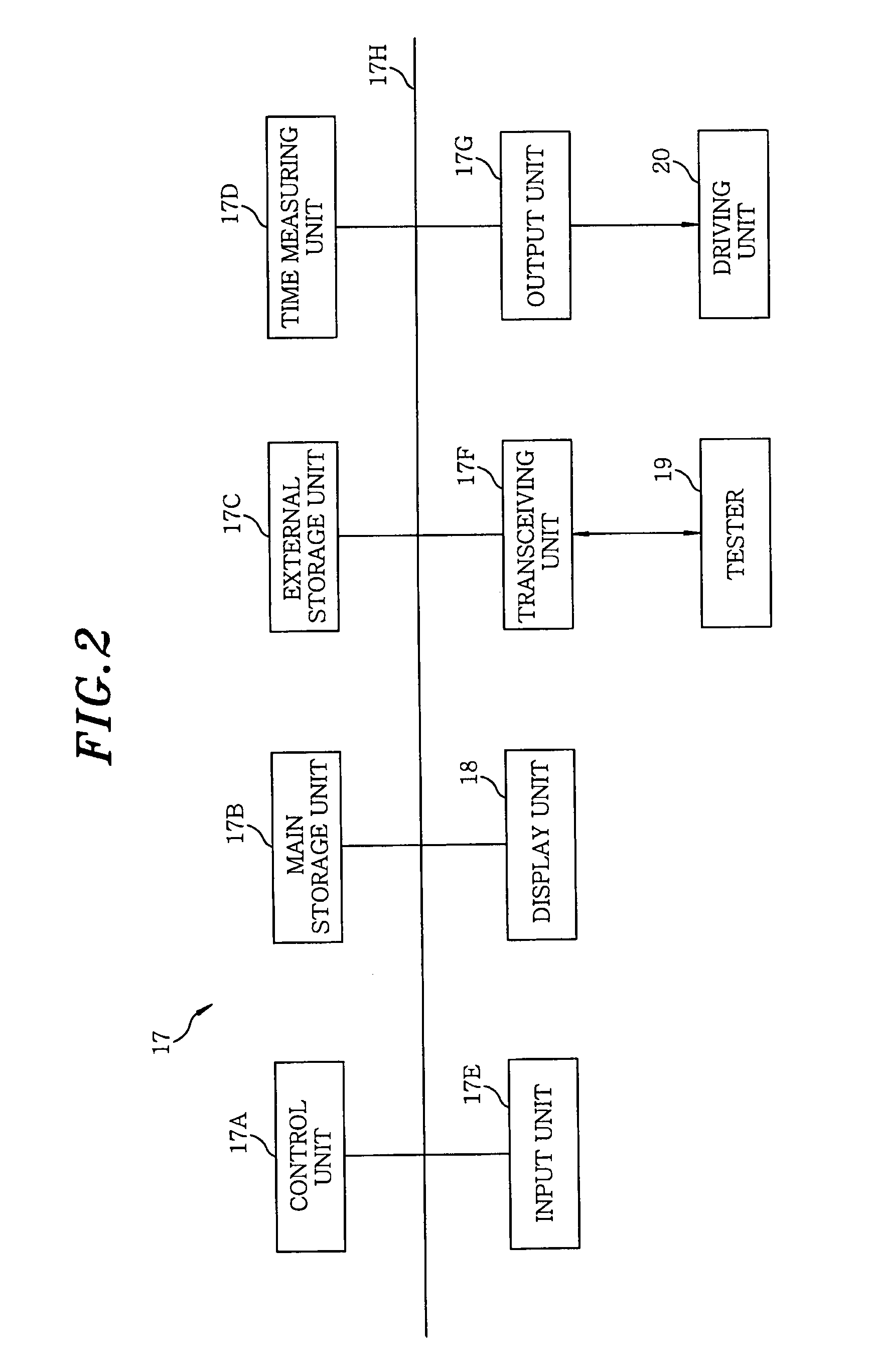
[0034]As shown in FIG. 1, a probe apparatus 10 includes: a loading unit 11 for transferring a wafer W as a target object to be inspected; and a prober chamber 12 provided near the loading unit 11 for inspecting electrical characteristics of the wafer W from the loading unit 11. The prober chamber 12 has: a mounting table 13 for mounting thereon the wafer W and moving in X, Y, Z and θ directions; a probe card 14 disposed above the mounting table 13; a test head T to be electrically contacted with the probe card 14 via an insert ring 15; an alignment mechanism 16 for aligning a plurality of probes 14A of the probe card 14 with the wafer W mounted on the mounting table 13; and a control device 17 mainly including a computer fo...


PUM


Abstract

An inspecting method includes registering a pre-obtained relationship between contact time of the probes with the target object having the predetermined temperature and tip positions of the probes which vary in accordance with the contact time. The method further includes inspecting the chips by estimating the tip positions of the probes based on the relationship and the contact time of the probes with the chips upon the inspection and then correcting the tip positions of the probes from previous tip positions based on the estimated values until the probes are stable without being extended or contracted during the inspection.

Description

FIELD OF THE INVENTION[0001]The present invention relates to an inspecting method using a probe apparatus; and, more particularly, to an inspecting method capable of performing high-temperature inspection as well as low-temperature inspection by using a probe apparatus without heating or cooling a probe card in advance to thereby increase an operating efficiency, and a storage medium storing a program of the method.BACKGROUND OF THE INVENTION[0002]A conventional probe apparatus includes: a loader chamber for transferring a target object to be inspected such as a semiconductor wafer or the like; a prober chamber for inspecting electrical characteristics of the target object transferred from the loader chamber; and a control unit for controlling the loader chamber and the prober chamber. The conventional probe apparatus serves to transfer the target object from the loader chamber to the prober chamber, inspect the electrical characteristics of the target object in the prober chamber, ...

Claims


Application Information

Patent Timeline
Patent Type & Authority Applications(United States)
IPC IPC(8): G01R31/28
CPCG01R31/2891G01R31/26H01L22/00
Inventor TANAKA, HIDEAKIAKASAKA, TOSHIAKI
Owner TOKYO ELECTRON LTD
Learn More