Examination apparatus, method for controlling examination apparatus, system, light guide, and scale

a control method and examination apparatus technology, applied in the direction of instruments, applications, image enhancement, etc., can solve the problems of positioning displacement on the skin to be observed, inspection is more complicated, and inspection is not easy to operate, so as to prevent image displacement of the lesion, high-reliable inspection, and accurate and efficient diagnosis.

Active Publication Date: 2021-03-02
DERMA MEDICAL
View PDF13 Cites 1 Cited by
  • Summary
  • Abstract
  • Description
  • Claims
  • Application Information

AI Technical Summary

Benefits of technology

[0016]The present invention prevents image displacement of a lesion in a skin, a mucosa, an epithelial cell structure, and the like due to displacement of an inspection position by module replacement, and provides highly-accurate and efficient diagnoses. Furthermore, the present invention enables to digitally store a single image as a patient name, an affected part, and a dermoscope image, and provides highly-reliable inspections without misidentification of patients, affected parts, and images.

Problems solved by technology

In conventional cases, a dermoscope must be kept away from the skin upon replacement of the modules, thereby causing positional displacement on the skin to be observed and making the inspection more complicated; this also needs skills for obtaining inspection accuracy.
Furthermore, the conventional dermoscope has required high-intensity light beam for detecting so-called diffuse reflection, which is reflected after passing through the epidermis and reaching the dermal layer, and thus accompanies with an enlarged power supply, an expanded scale of devices, increased weight, and the like, thereby resulting in not good operability.
In addition, there has been a problem in that they are not available for medical observation with well distinguishing between direct reflection from the epidermis and diffuse reflection.

Method used


Image

  • Examination apparatus, method for controlling examination apparatus, system, light guide, and scale
  • Examination apparatus, method for controlling examination apparatus, system, light guide, and scale
  • Examination apparatus, method for controlling examination apparatus, system, light guide, and scale

Examples


embodiment 200

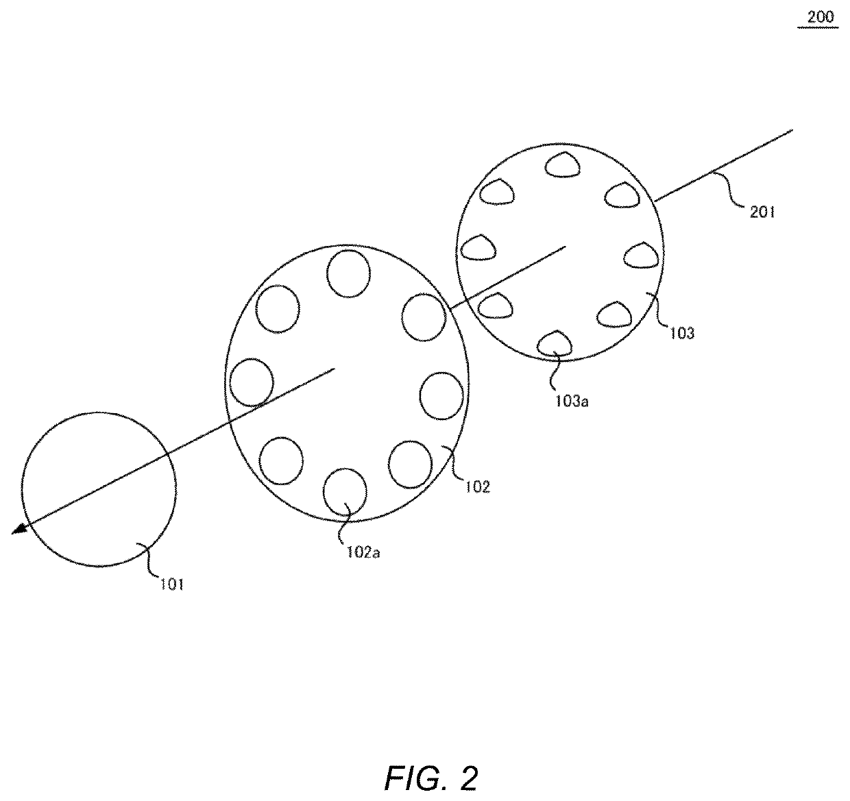
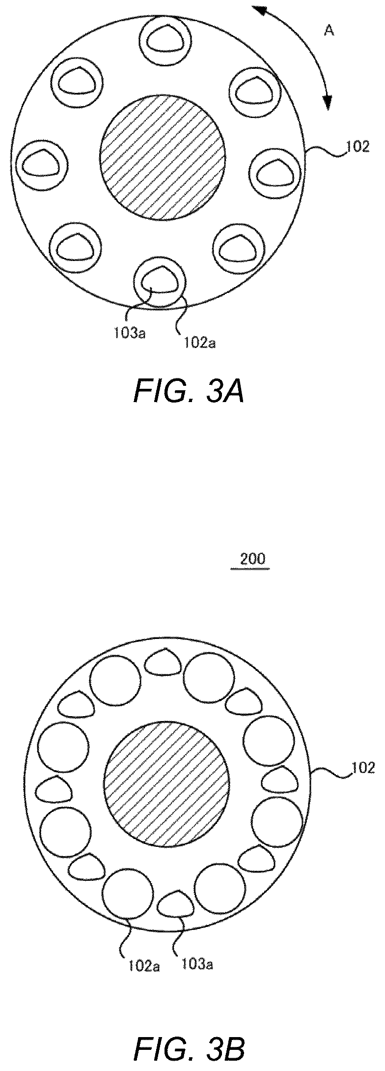
[0046]FIG. 3 shows an embodiment 200 of the positions of the LEDs 103a and the polarization state-regulating parts 102a for achieving a direct mode and a polarization mode of the embodiment. FIG. 3(a) shows positions for providing a direct mode, and FIG. 3(b) shows positions for providing a polarization mode. In the direct mode shown in FIG. 3(a), the LEDs 103a and the polarization state-regulating part 102a may be aligned, and a tissue may be directly exposed with light from LED 103a.

[0047]Incidentally, the direct mode in the embodiment may be a mode in which light from the LEDs 103a is exposed to a tissue as random mixture of linearly polarized light (non-polarized) due to inner scattering. In FIG. 3(a), the reflected light may pass through a hatched region of the circular polarization filter 102 and may be imaged by the imaging device 106.

[0048]On the other hand, the polarization mode shown in FIG. 3(b) may be a mode in which, upon rotation of the LED holder 103 in the direction...

second embodiment

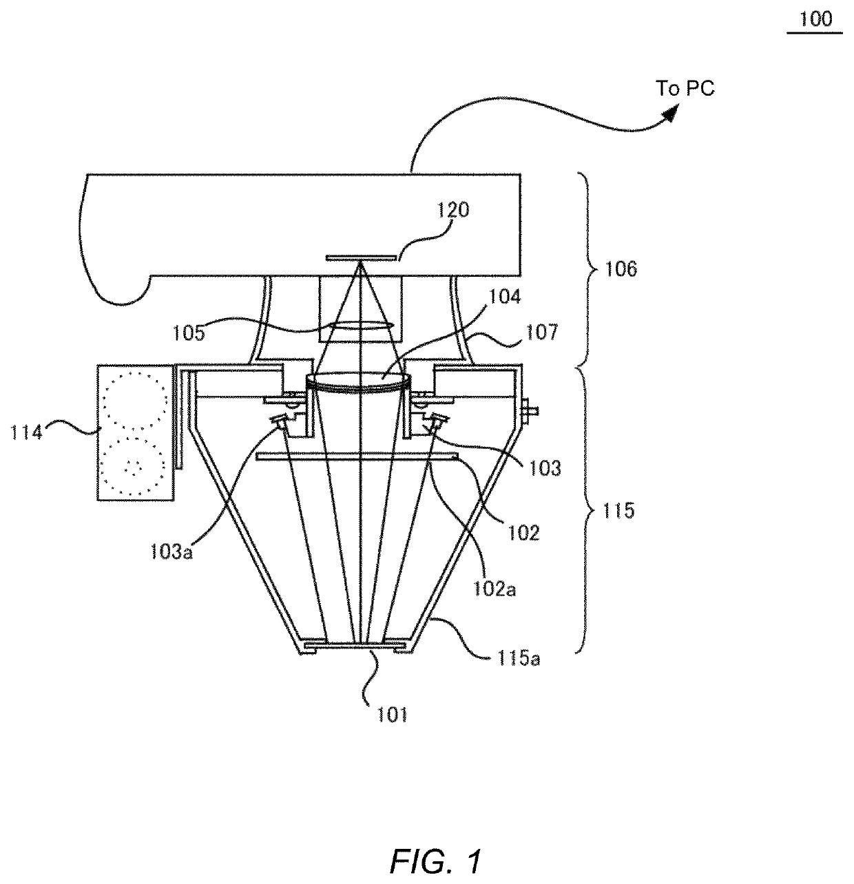
[0070]The inspection module 115 of the second embodiment may be one in which an eyepiece part 710 is further added to the inspection module 115 shown in FIG. 1, and may form the light focused at the objective lens 104 into nearly parallel light beams at a concave lens 711, thereby allowing for direct observation by a physician. In a further embodiment, the configuration may be one in which an optical fiber is connected to the eyepiece part 710, an image is sent to the imaging device 106 remotely installed, and then the image from the inspection module 115 is confirmed on a liquid crystal display device on the body of the imaging device 106 or on a display device in an information-processing device by a physician. Thus, the embodiment shown in FIG. 7 may enable an inspector such as a physician to pay attention for inspections without forcing to take an unnatural posture.

[0071]The embodiment shown in FIG. 7 may allow to reduce manual operation to the inspection device 100 only to the ...

first embodiment

[0077]Then, at step S905, the first digital image and the second digital image may be registered in association with personal identification information of a patient. In such case, the registration may be performed in the imaging device 106 itself, or may be directly recorded in an information-processing device connected to the imaging device 106, as similar with the The control method in FIG. 9 may then finish at step S906.

[0078]The second embodiment may allow a physician to perform inspection as well as to take informed consent from a patient with showing a display device in an information-processing device, and thus may provide medical care with higher patient satisfaction. In addition, a physician may enable to perform inspection apart from the spatial position of the imaging device 106 using a more enlarged image, thereby also providing improvement of inspection quality.

[0079]FIG. 10 shows an embodiment of an inspection system 1000 using the inspection device 100 of the embodi...


PUM


Abstract

[Technical Problem]To provide an inspection device for inspecting a tissue using reflected light from a tissue, and a control method, a system, a light guide, and a scale of the inspection device.[Solution to Problem]An inspection device 100 of the present invention comprises an imaging device 106 and an inspection module 115 for allowing the imaging device 106 to take a tissue image. The inspection module 115 includes an objective lens 104 for focusing reflected light from a tissue to the imaging device 106; a plurality of LEDs 103a for surrounding the optic axis of the objective lens 104 and exposing light to the tissue; a circular polarization filter 102 comprising polarization state-regulating parts 102a for exposing the light from the LEDs 103a to the tissue directly or as circularly polarized light; and an alignment mechanism 110a for aligning the polarization state-regulating part 102a with the position of the LED 103a.

Description

TECHNICAL FIELD[0001]The present invention relates to an inspection device, a control method, system, light guide and scale of the inspection device, and more particularly relates to an inspection device for inspecting a skin, a mucosa, an epithelial cell structure using a reflected light from a skin; and a control method, a system, a light guide and a scale of the inspection device.BACKGROUND ART[0002]Digital dermoscopes have been conventionally and regularly known as devices and inspection methods that take an enlarged image of pigmentation or the like in a predetermined size of skin with a digital camera. The devices allow for inspecting pigmentation condition of skin tissue through the skin surface to around the dermis with attaching a dermoscope module to a digital camera so as to separately observe respective reflected lights that are reflected on the skin surface and after reaching the dermis. Such digital dermoscopes that have been proposed also include a system that enables...

Claims


Application Information

Patent Timeline
Patent Type & Authority Patents(United States)
IPC IPC(8): G06K9/00A61B5/00G06T7/00F21V9/14A61B10/00F21W131/20F21Y115/10
CPCA61B5/0077A61B5/00A61B5/441A61B10/00F21V9/14G06T7/0012F21W2131/20F21Y2115/10G06T2207/30088A61B5/444A61B5/0082A61B5/1072A61B5/1079
Inventor SHINOZAKI, TAKASHI
Owner DERMA MEDICAL
Why Eureka
Try Eureka