Anti-sway control of a crane under operator's command

A manipulator, anti-sway technology, applied in the direction of cranes, cranes, load suspension components, etc. of trolleys

Inactive Publication Date: 2004-06-16
NAT UNIV OF SINGAPORE
View PDF7 Cites 29 Cited by
  • Summary
  • Abstract
  • Description
  • Claims
  • Application Information

AI Technical Summary

Problems solved by technology

Since Overton is a variant of Vi...

Method used


Image

  • Anti-sway control of a crane under operator's command
  • Anti-sway control of a crane under operator's command
  • Anti-sway control of a crane under operator's command

Examples


Embodiment Construction

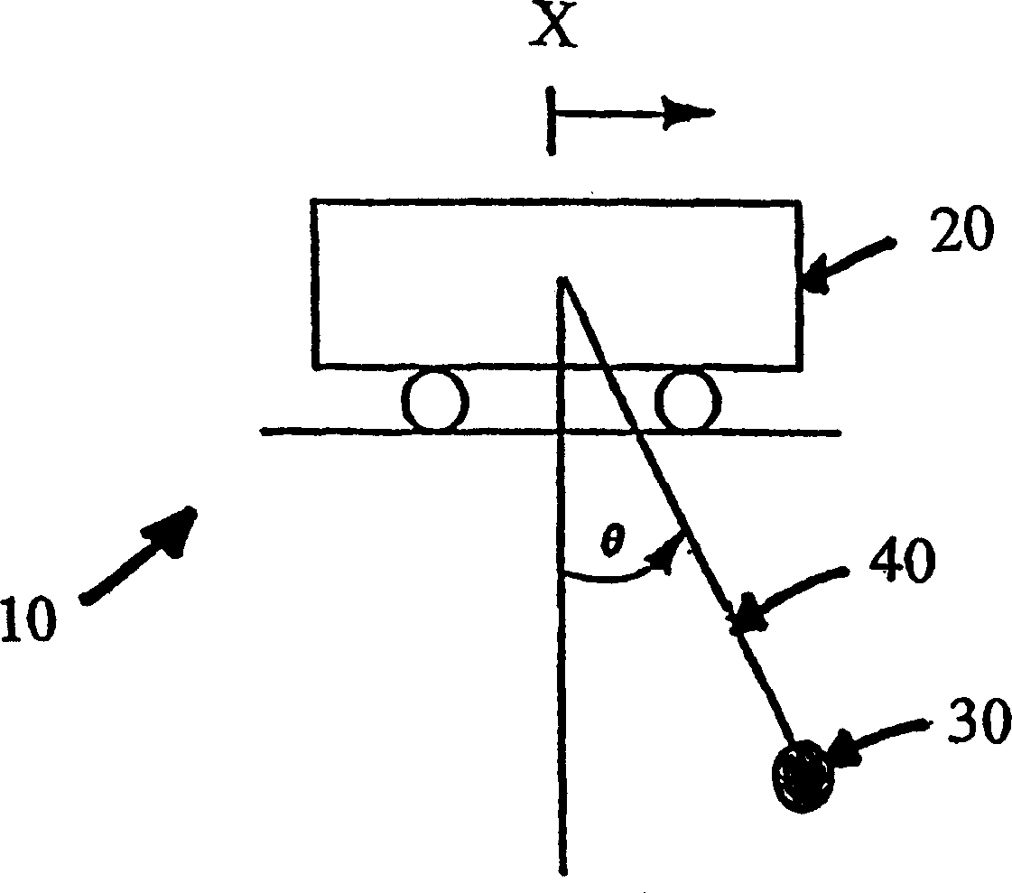
[0031] refer to figure 1 , shows a model of the crane system 10 . Crane system 10 includes a tackle 20 having a hoist (not shown) to adjustably suspend payload 30 by rope 40 . The swing angle θ is generated between the position of the rope 40 at rest and the position of the rope 40 during the swing oscillation. The differential equation describing the development of the sway angle θ of the payload 30 over time is:

[0032] l ( t ) θ . . ( t ) + 2 l . ( t ) θ . ( t ) + g sin θ ( t ) = x . ...


PUM


Abstract

A system (10) is disclosed for eliminating sway of a load (30) in a crane or crane-like system subject to operator's command. The load is suspended by a cable (40) from a horizontally movable trolley (20) and can be hoisted vertically. The system uses the principle of cancellation to eliminate sway even when the crane has simultaneous trolley and hoisting motions. The system takes into account the full dynamical effect in computing cancellation signals. The use of a family of ordinary differential equations for the computation of the cancellation controls is a key component of the invention. In computing these controls, the differential equations are solved in real time using sensory measurement of the cable length and its time derivative. The cancellation controls handle the sway induced by the operator's command. Sway can also be induced by other factors, like wind load and external disturbances. This system also includes a feedback mechanism for eliminating sway due to such factors. The system ensures saturation limits, corresponding to the velocity and acceleration limits of the drive system of the trolley are not exceeded for proper functioning of the system.

Description

technical field [0001] The present invention relates to a system and method for controlling a rope-suspended payload transfer system, and more particularly, to a system and method for anti-sway control of a payload undergoing horizontal trolley and vertical lifting motion. Background technique [0002] Gantry cranes are widely used in port operations for the transfer of containers. Typically, the crane has two inputs in the form of speed commands. These two velocity commands independently control the horizontal carriage and vertical lift motion of the payload. Undesired swaying of the payload at the end of the transport is a difficulty in completing the transfer movement. Loading or unloading operations cannot be achieved while the payload is swaying. Currently, only experienced manipulators can effectively bring containers to a no-sway standstill. Other manipulators must wait for the swing to stop. Typically, the time spent waiting for the swing to stop or performing v...

Claims


Application Information

Patent Timeline
IPC IPC(8): B66C13/22B66C13/06
CPCB66C13/063B66C13/06
Inventor 王宗仁埃尔默·G·吉尔伯特
Owner NAT UNIV OF SINGAPORE
Why Eureka
Try Eureka