Force excitation protection circuit suitable for direct-current injection type rotor grounding protection measurement loop

A technology of rotor grounding and protection measurement, which is applied in the direction of emergency protection circuit devices and electrical components, which can solve the problems of protection refusal, damage of components in the measurement circuit, and large current flow, so as to prevent protection refusal and increase fault tolerance sexual effect

Active Publication Date: 2020-11-17
NANJING GUODIAN NANZI POWER GRID AUTOMATION CO LTD
View PDF4 Cites 0 Cited by
  • Summary
  • Abstract
  • Description
  • Claims
  • Application Information

AI Technical Summary

Problems solved by technology

[0004] However, there are still some problems with the above protection methods. For example, when the rotor is strongly excited and the positive pole is metallically grounded, a large current will flow through the measurement circuit, which may easily cause the measurement circuit to The components are damaged, but if the circuit parameters are designed according to the maximum strong excitation voltage, the resistance measurement accuracy will be insufficient
[0005]In addition, when the rotor has no ground fault, the measurement circuit has no path, and the rotor leakage current is always zero, so the self-test of the measurement circuit cannot be performed, and the measurement cannot be obtained in time and accurately Whether there is a fault in the circuit, it is easy to cause the protection to refuse to operate when the rotor has a ground fault

Method used


Image

  • Force excitation protection circuit suitable for direct-current injection type rotor grounding protection measurement loop
  • Force excitation protection circuit suitable for direct-current injection type rotor grounding protection measurement loop
  • Force excitation protection circuit suitable for direct-current injection type rotor grounding protection measurement loop

Examples


Embodiment 1

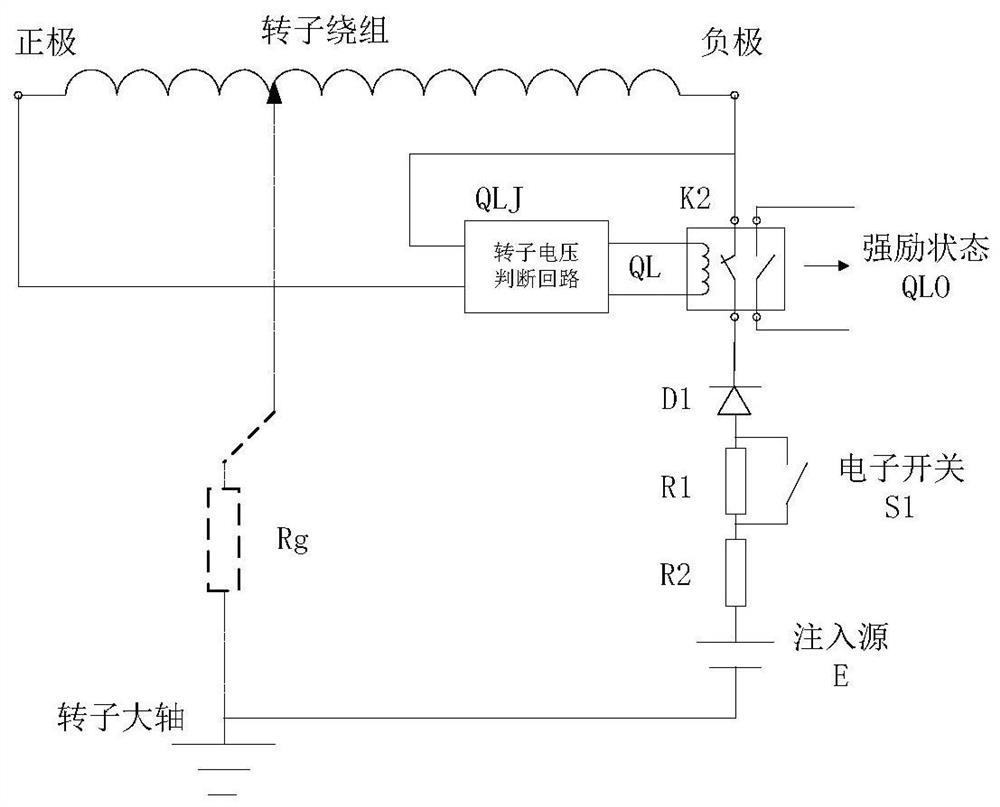
[0035] This embodiment introduces the strong excitation protection circuit suitable for the measurement circuit of the DC injection rotor grounding protection, refer to image 3 As shown, the forced excitation circuit includes a relay K2 and a rotor voltage detection circuit QLJ.

[0036] The rotor voltage detection circuit QLJ includes resistor R3, resistor R4, and voltage regulator tube D2. The positive pole of the rotor is connected to one end of resistor R3, the other end of resistor R3 is connected to one end of resistor R4 and the negative pole of voltage regulator tube D2, and the negative pole of the rotor is negative. The input is connected to the other end of the resistor R4, and the anode of the regulator tube D2 outputs a strong excitation signal QL.

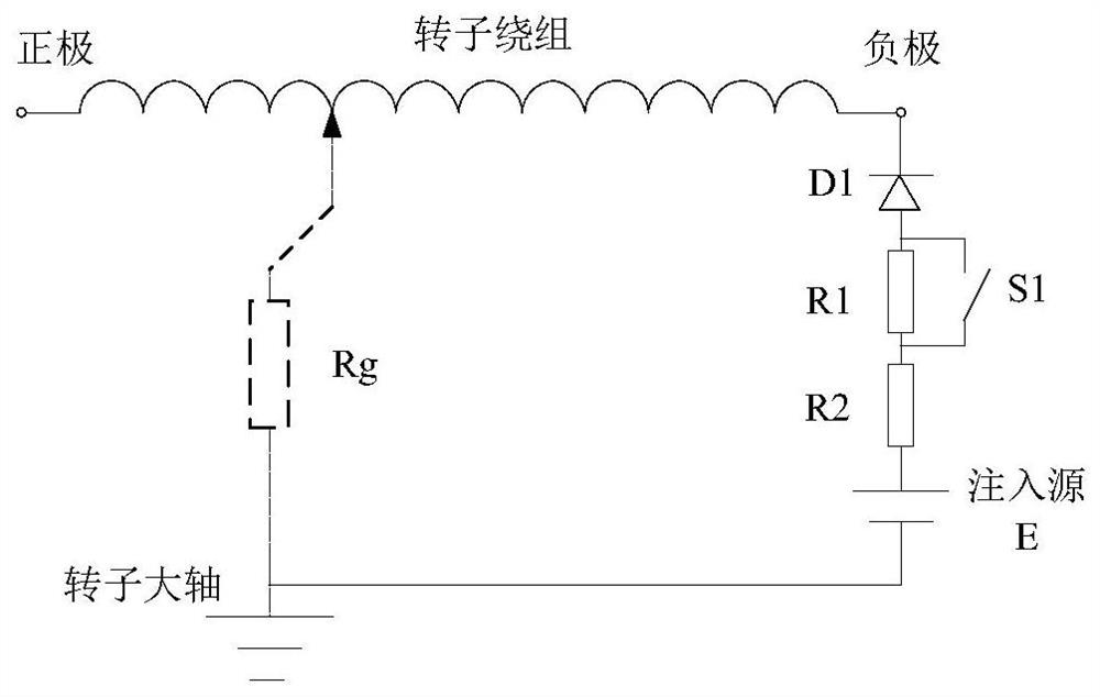
[0037] The large shaft of the rotor is connected to the negative pole of the common terminal of the DC injection power supply E, the positive pole of the DC injection power supply E is connected to one end of the res...

Embodiment 2

[0041] On the basis of embodiment 1, this embodiment refers to Figure 4 As shown, the positive and negative poles of the rotor are connected to the rotor voltage judgment circuit QLJ through the rectification circuit ZL. At this time, regardless of whether the positive and negative poles of the rotor are reversed, the output voltage is positive, and the positive and negative polarities of the strong excitation protection circuit are added. fault tolerance.

Embodiment 3

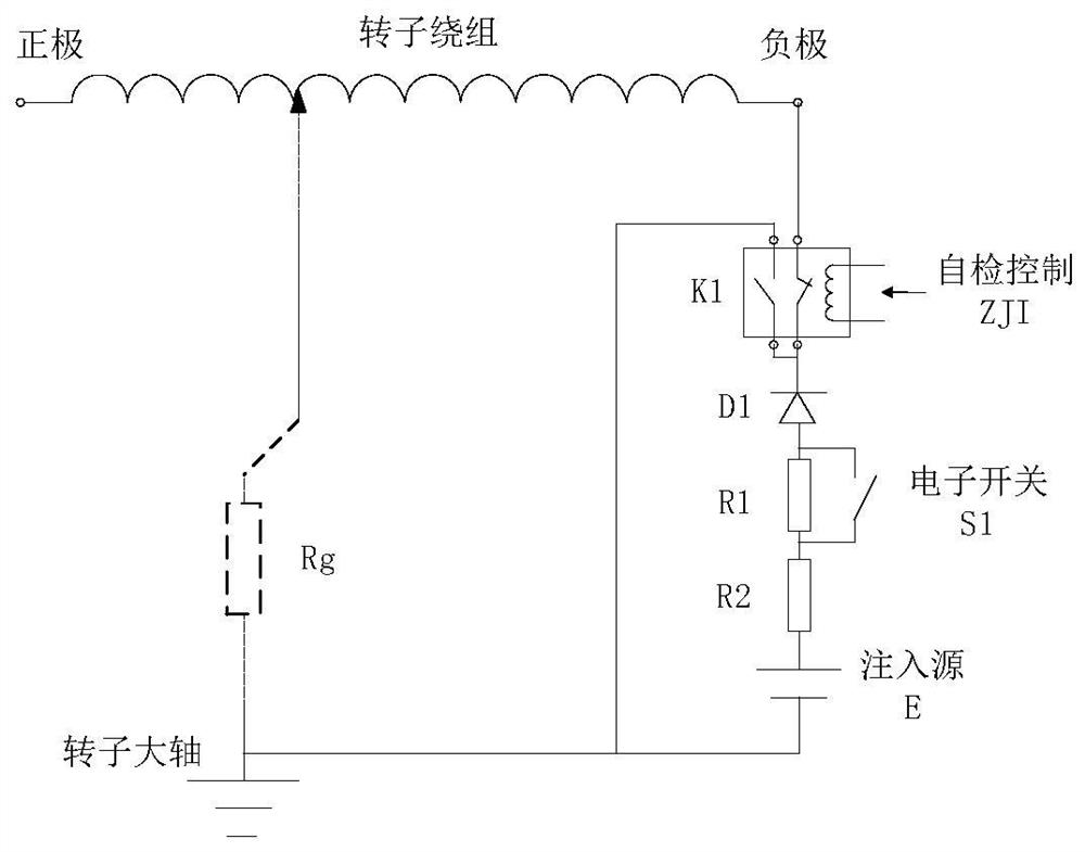
[0043] In order to realize the self-inspection of the measurement circuit, this embodiment introduces a self-inspection circuit suitable for the measurement circuit of the DC injection rotor grounding protection, refer to figure 2 As shown, the self-test circuit includes a relay K1, and the relay K1 includes a normally closed contact and a normally open contact; the first end of the normally closed contact of K1 is connected to the negative pole of the rotor, and the second end is injected with DC through D1, R1, R2. The source is connected to the main shaft of the rotor; the first end of the normally open contact of K1 is connected to the main shaft of the rotor, and the second end is connected to the second end of the normally closed contact of K1; the coil of K1 is connected in a self-test control loop.

[0044] The conduction of the self-test control circuit will make the K1 coil conduct, so that the K1 normally closed contact is disconnected, the original measurement circ...


PUM


Abstract

The invention discloses aforce excitation protection circuit suitable for a DC injection type rotor grounding protection measurement loop. The measurement loop comprises an injection DC source connected in series between a rotor large shaft and a rotor negative electrode, at least two resistors, a controllable switch connected in parallel to two ends of one of the resistors, and a diode. The forceexcitation protection circuit comprises a relay K2 and a rotor voltage detection unit. The relay K2 comprises a normally-closed contact which is connected in series in the DC injection type rotor grounding protection measurement loop, and the two ends of a coil of the relay K2 are connected with the rotor voltage detection unit. The rotor voltage detection unit is connected with a rotor positiveelectrode and a rotor negative electrode to detect a rotor voltage, and is communicated with the rotor positive electrode, the rotor negative electrode and a coil of the relay K2 according to a comparison result of the rotor voltage and a set voltage threshold value, so that a rotor winding forms a current loop with the coil of the relay K2 through a rotor voltage judgment unit. According to the invention, when the rotor is forcibly excited and the positive electrode is in metallic grounding, components of the measurement loop are prevented from being damaged by a large current flowing throughthe measurement loop.

Description

technical field [0001] The invention relates to the technical field of generator operation monitoring and protection, in particular to a forced excitation protection circuit suitable for a DC injection type rotor grounding protection measurement circuit. Background technique [0002] As an important part of the generator, the generator rotor winding provides the generator with a rotating rotor magnetic field, cuts the stator winding, and generates electricity. The common fault forms of rotor winding insulation damage are one-point grounding of the rotor winding and two-point grounding of the rotor winding. The grounding fault of one point of the rotor winding does not cause harm to the generator, but if the second point grounding occurs successively, it will cause vibration of the generator. In severe cases, the shafting and turbine may be magnetized, so it is necessary to configure injection or ping-pong rotor grounding protection to protect the rotor from a single groundin...

Claims


Application Information

Patent Timeline
IPC IPC(8): H02H7/06
CPCH02H7/06
Inventor 包明磊桑建斌朱宇聪李玉平李明
Owner NANJING GUODIAN NANZI POWER GRID AUTOMATION CO LTD
Why Eureka
Try Eureka