Drum type washing machine

A drum-type washing machine, drum technology, applied in the field of washing machines, can solve the problems of time-consuming and cost-increasing

Inactive Publication Date: 2004-06-30
SANYO ELECTRIC CO LTD
View PDF0 Cites 12 Cited by
  • Summary
  • Abstract
  • Description
  • Claims
  • Application Information

AI Technical Summary

Problems solved by technology

[0006] Because of such users, although there are maintainers (workers at the point of sale, etc.) who disassemble the washing machin...

Method used


Image

  • Drum type washing machine
  • Drum type washing machine
  • Drum type washing machine

Examples


Embodiment Construction

[0041] Hereinafter, embodiments of the present invention will be specifically described with reference to the drawings.

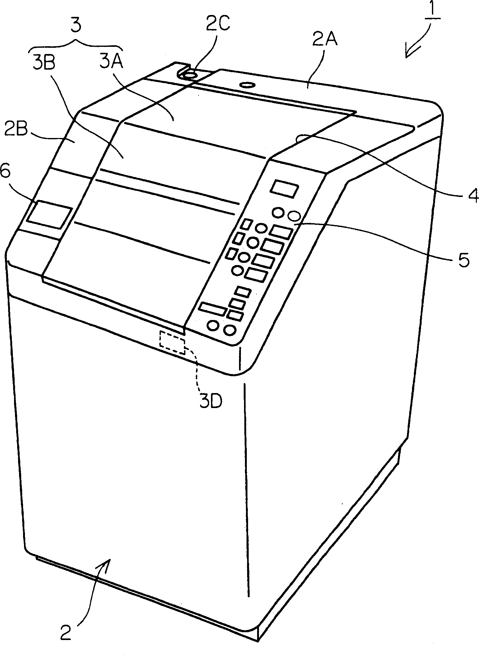
[0042] figure 1 It is a perspective view showing the appearance structure of the drum type washing machine 1 according to an embodiment of the present invention.

[0043] The front-loading washing machine 1 is, for example, defined by a box 2 having a substantially rectangular parallelepiped shape. On the front side of the upper surface 2A of the case 2, for example, an inclined surface 2B is formed, which is inclined toward the lowered state toward the front side.

[0044]The outer cover 3 has, for example, a rear cover 3A covering the rear side of the opening 4 and a front cover 3B covering the front side. The rear end portion of the rear cover 3A is rotatably attached to the upper surface 2A of the case 2, and the rear end portion of the front cover 3B is rotatably attached to the front end portion of the rear cover 3A. The user holds the handle 3C fo...


PUM


Abstract

In response to turning on a cleaning key (Yes in STEP S1), the washing machine starts a cleaning mode and releases a lock for the drum (STEP S3). After a user rotates the drum to a desired rotating position while turning on the cleaning key (Yes in STEP S5), he/she can stop the drum at the rotating position through an electric brake by turning off the cleaning key (NO in Step S5) and clean the outer peripheral surface of the drum. While cleaning the whole outer peripheral surface of the drum easily, he/she confirms that the drum is properly cleaned by repeating the operation.

Description

technical field [0001] The invention relates to a washing machine which stores laundry in a drum for washing. Background technique [0002] There is known a front-loading washing machine in which laundry is stored in a substantially cylindrical drum (washing tank) that is rotatable about an axis extending substantially in the horizontal direction and washed. Such a washing machine may have, for example, an outer tank surrounding the outside of the drum. By rotating the drum while a certain amount of water is stored in the outer tank, the washing in the drum is repeatedly lifted from the inner surface of the drum to protrude from the baffle. The plate is lifted and naturally dropped from a certain height to the water surface (vibration washing) to perform washing. [0003] Recently, general users are highly concerned about the outer surface of the washing tub surrounded by the outer tub (user Out of sight) attached detergent deposits or reports of black mold. [0004] In t...

Claims


Application Information

Patent Timeline
IPC IPC(8): D06F37/04D06F23/02D06F33/02D06F37/10D06F39/08
CPCD06F35/008D06F37/04D06F37/28D06F33/43D06F34/28D06F2105/54
Inventor 村上穂幸本田国兴尾关祐仁竹内晴美
Owner SANYO ELECTRIC CO LTD
Why Eureka
Try Eureka