Electric vacuum cleaner

A vacuum cleaner, electric technology, applied in the direction of vacuum cleaners, suction filters, devices for cleaning filters, etc., can solve problems such as damage to indoor hygiene, and achieve the effect of excellent hygiene conditions

Inactive Publication Date: 2004-07-14
SHARP KK
View PDF2 Cites 10 Cited by
  • Summary
  • Abstract
  • Description
  • Claims
  • Application Information

AI Technical Summary

Problems solved by technology

At this time, the problem of detrimental to indoor hygiene occurs

Method used


Image

  • Electric vacuum cleaner
  • Electric vacuum cleaner
  • Electric vacuum cleaner

Examples


Embodiment Construction

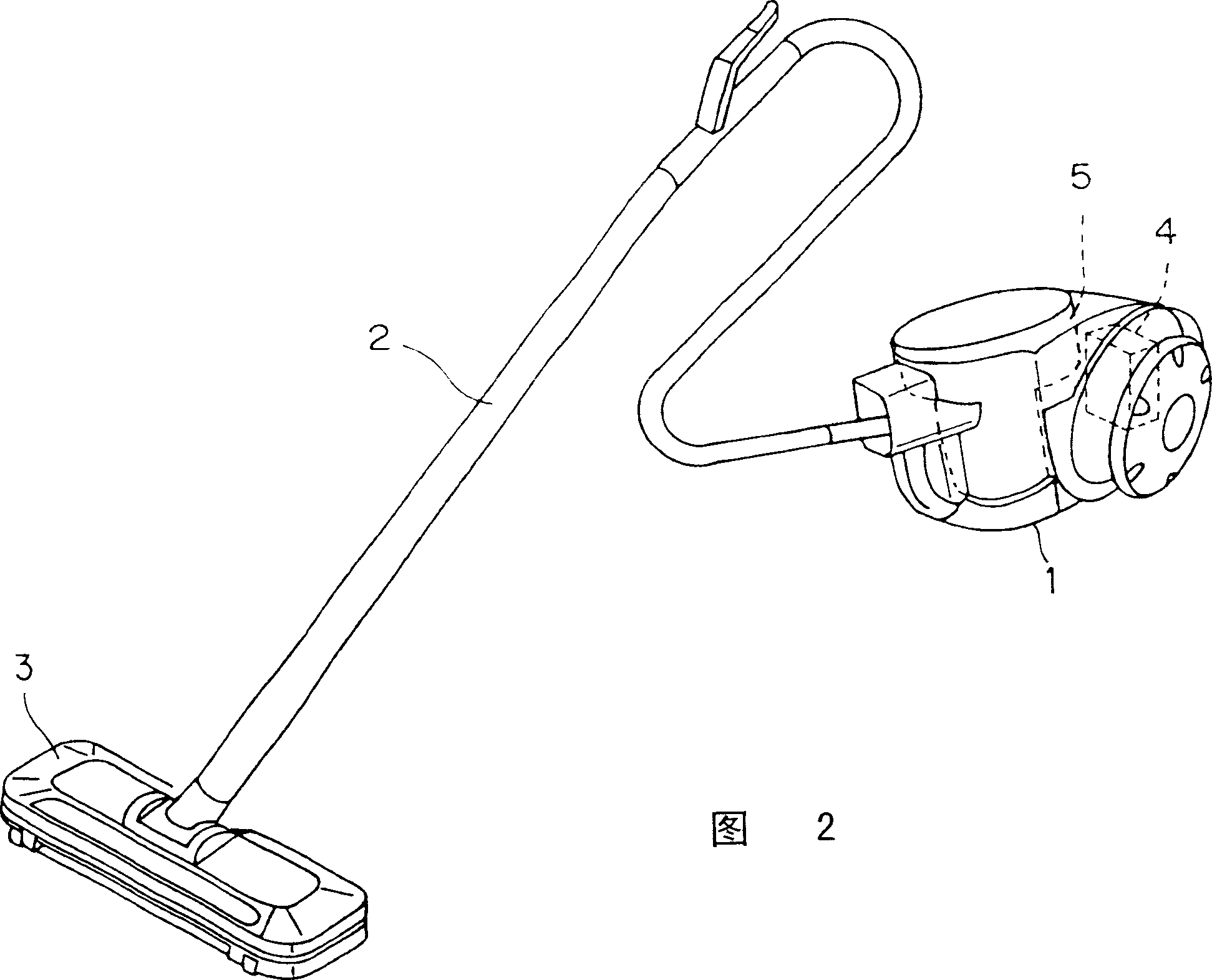
[0031] Below, according to Figure 1 to Figure 13 An example of the present invention will be described. Fig. 2 schematically shows the structure of the electric vacuum cleaner of the present invention.

[0032] The electric vacuum cleaner of the present invention has a vacuum cleaner body 1 , a connecting hose 2 and a suction port assembly 3 . The connecting hose 2 constitutes a supply passage for supplying the air sucked in from the suction port assembly 3 to the cleaner main body 1 . The suction port unit 3 sucks air through the air suction port (not shown) by the operation of the electric blower 4 shown below.

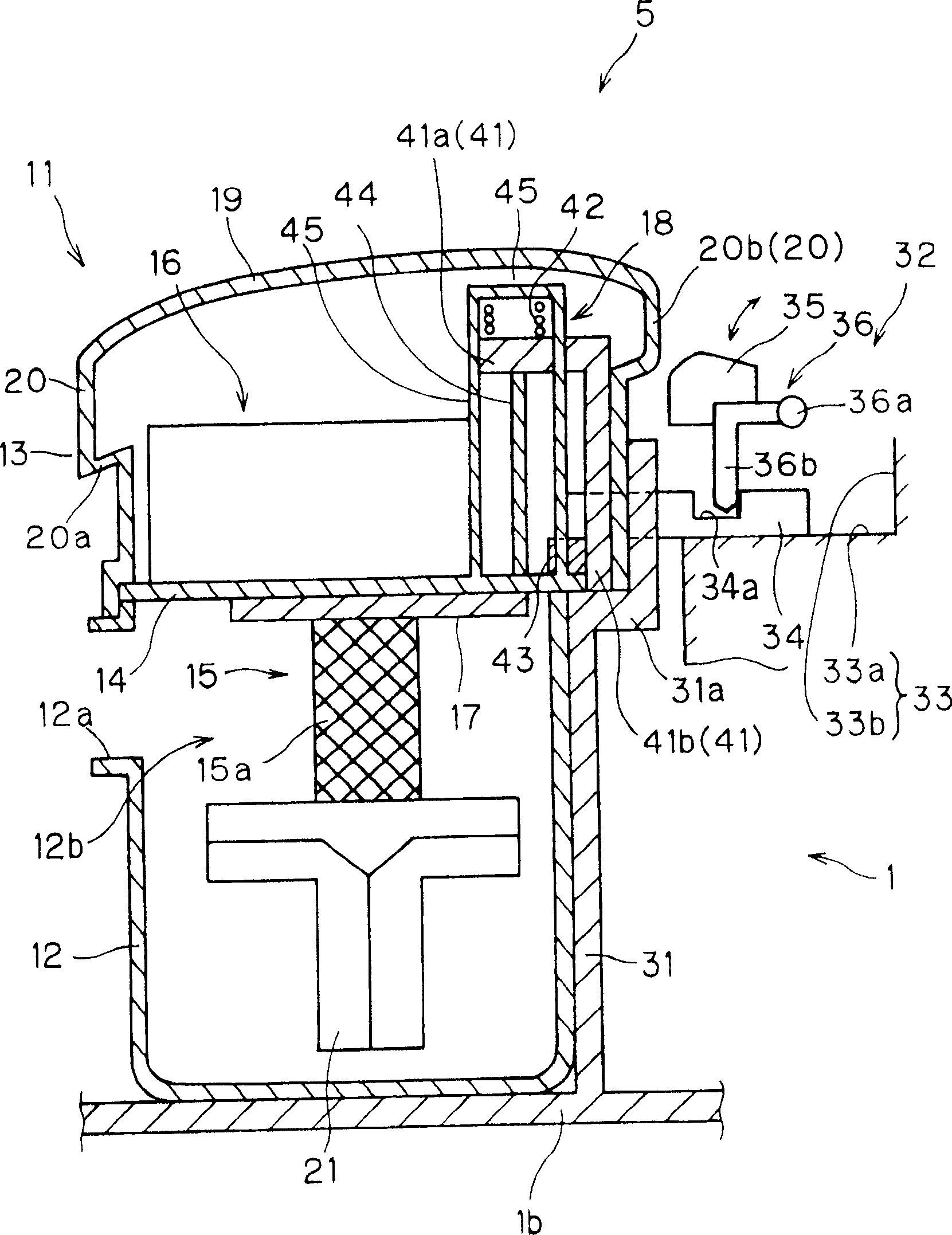
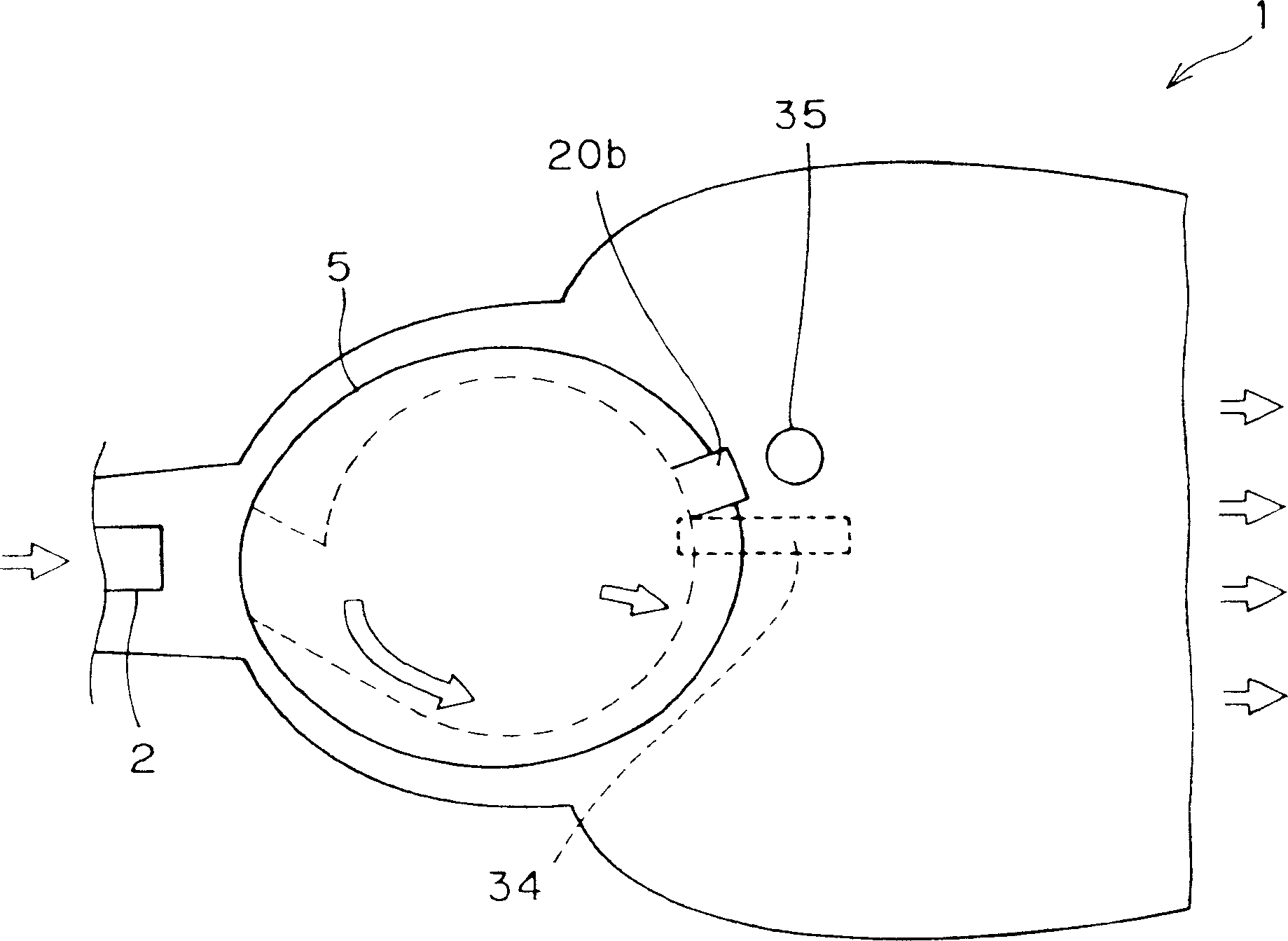
[0033] The vacuum cleaner body 1 has an electric blower 4 and a cyclone dust collector 5 . The electric blower 4 sucks air through the suction port assembly 3 , the connecting hose 2 and the cyclone dust collector 5 . The cyclone dust collector 5 is a mechanism for centrifuging dust contained in the air by swirling the air sucked by the electric blower 4 , and ...


PUM


Abstract

A cyclone body of the cyclone dust collector comprises a cleaning implement for cleaning the filter as sliding with the filter covering the surface of the exhaust pipe and a sliding means for sliding the cleaning implement and the filter as interlocking with the attaching/detaching of the cyclone dust collector to the cleaner body. The sliding means comprises a support part connected to the cleaning implement via a connection rod and supported by a positioning part mounted on the cleaner body side and a second energizing means for energizing a housing fixed to a fixed board with the support part as the fulcrum in the direction of taking out the cyclone dust collector from the cleaner body.

Description

[0001] This application is based on Japanese Patent Application (application number) No. 2002-382217 filed in Japan on December 27, 2002 and Japanese Patent Application No. 2003-61425 filed in Japan on March 7, 2003, all of which are hereby used as refer to. technical field [0002] The present invention relates to an electric vacuum cleaner with a cyclone dust collector that centrifugally separates the dust contained in the air by swirling the sucked air, and in particular relates to a method for cleaning the filter on the surface of the exhaust cylinder of the cyclone dust collector. Electric vacuum cleaner for sweeping. Background technique [0003] Various proposals have been made as a conventional electric vacuum cleaner provided with a cyclone dust collector. This cyclone dust collector has an exhaust tube with an exhaust port formed on its peripheral surface, and the air in which dust has been centrifuged is discharged to the outside through the exhaust tube. [000...

Claims


Application Information

Patent Timeline
Patent Type & Authority Applications(China)
IPC IPC(8): A47L9/16A47L5/00A47L9/20
CPCA47L5/362A47L9/1666A47L9/20
Inventor 大西裕二
Owner SHARP KK
Why Eureka
Try Eureka