Window opening apparatus

A window opener, push-pull rod technology, applied in door/window fittings, construction, wing fan control mechanisms, etc., can solve the problems of laborious, unsafe, and inconvenient window opening, and achieve the effect of convenient use.

Inactive Publication Date: 2004-07-21
梁国熙 +1
View PDF0 Cites 13 Cited by
  • Summary
  • Abstract
  • Description
  • Claims
  • Application Information

AI Technical Summary

Problems solved by technology

[0002] The sash of the existing windows is generally opened and closed by pushing the sash from left to right or by pushing and pulling the sash outward and inward by hand. You have to extend your arm out of the window to operate the opening and closing of the window sash, which is unsafe and inconvenient to use

Method used


Image

  • Window opening apparatus
  • Window opening apparatus
  • Window opening apparatus

Examples


Embodiment Construction

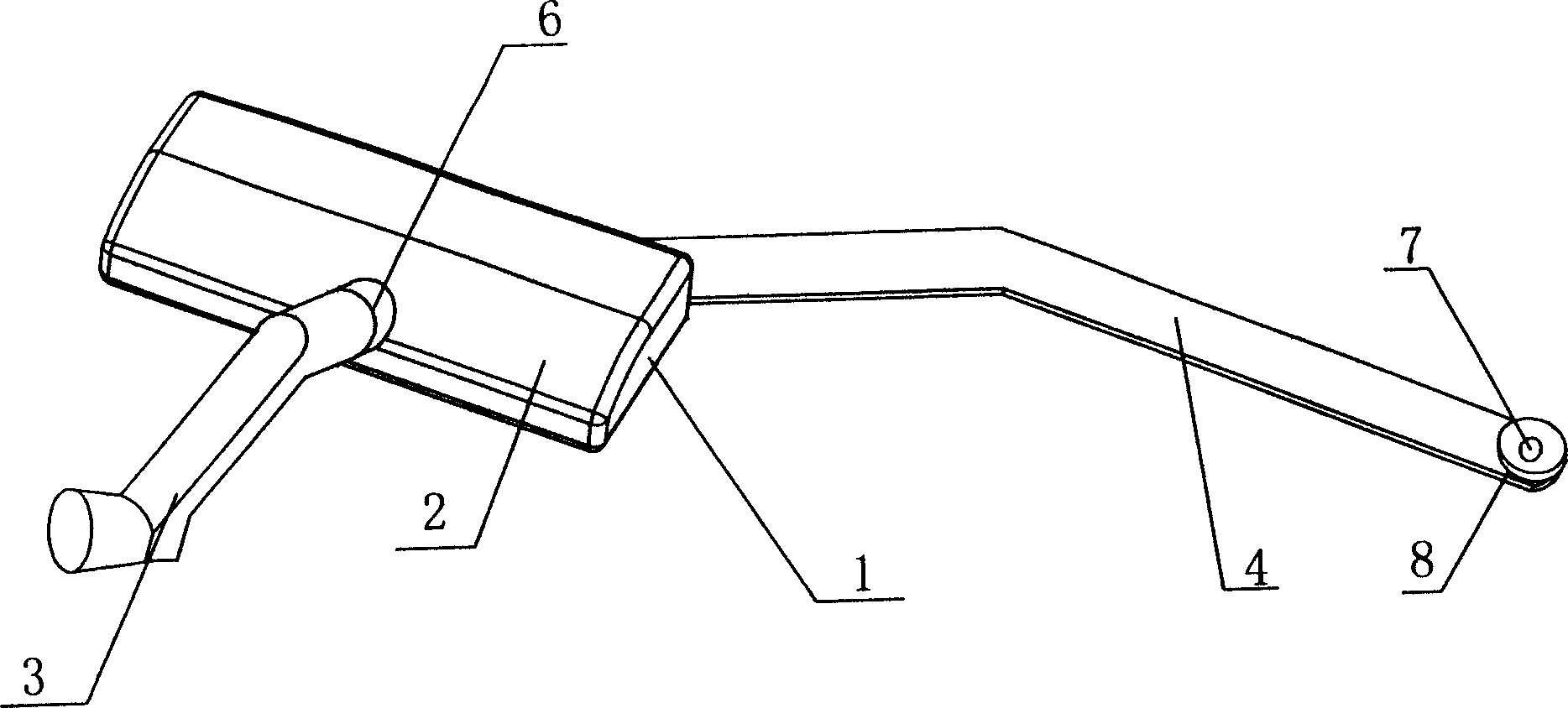
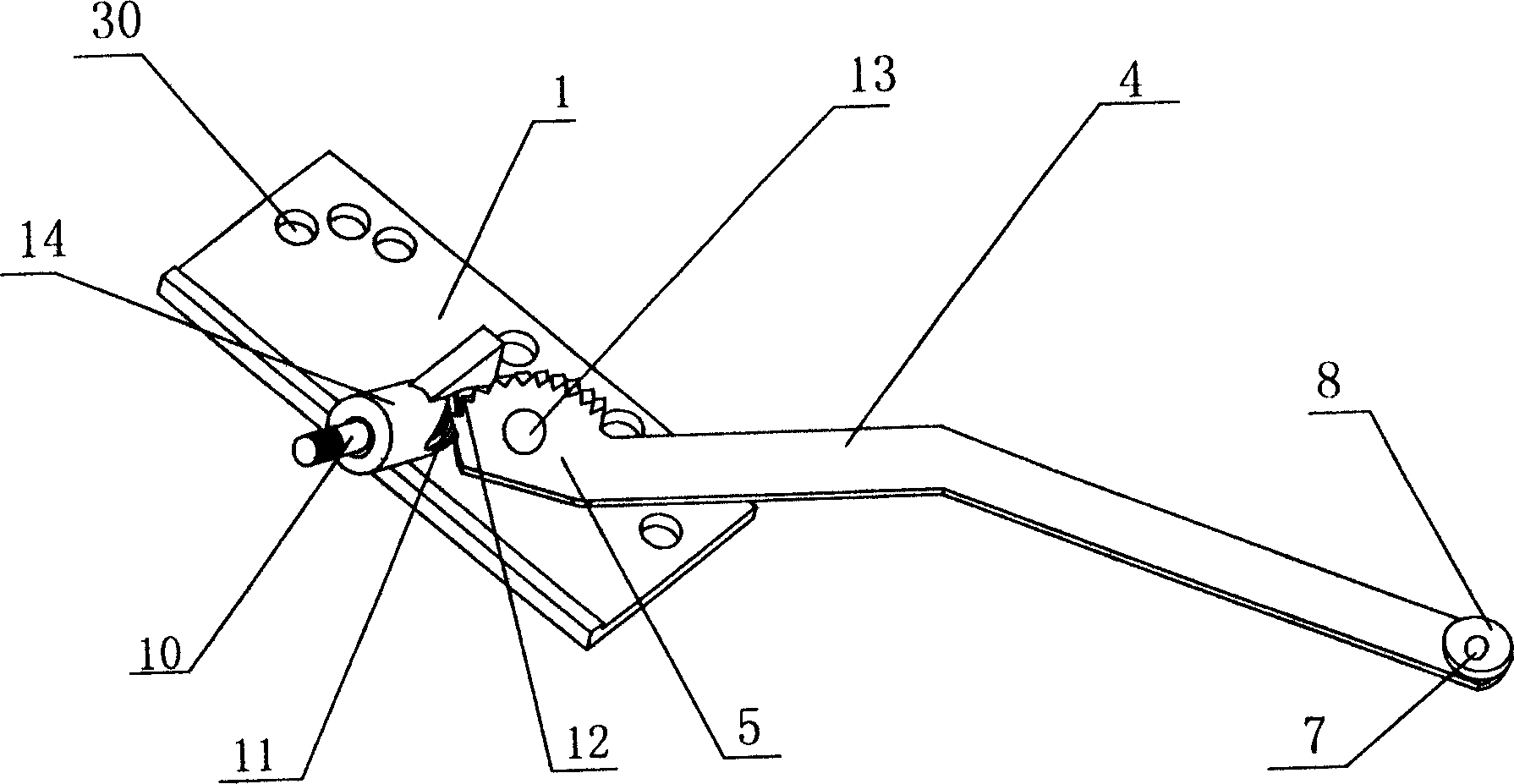
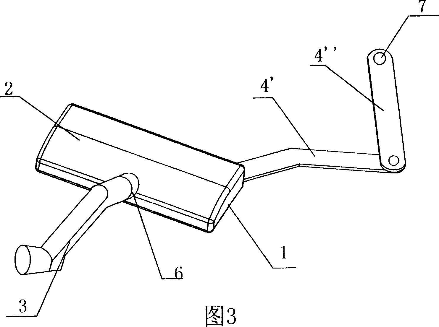
[0016] refer to figure 1 , figure 2 , a structural schematic diagram of Embodiment 1 of the present invention, and its structure is as follows: the window opener includes a base 1 and an upper cover 2, and the base 1 has a mounting hole 30 for fixing the window opener on the window frame, through which the worm 10 passes. The hole 6 of the upper cover 2 is fixed between the base 1 and the upper cover 2. The upper end of the worm 10 and the handle 3 are installed and connected through the inner spline at the bottom of the handle and the spline provided on the top of the worm. The lower end of the worm 10 The part is placed on the base 1, and the worm 10 is fixed between the base 1 and the upper cover 2 through the inclined mounting column 14 installed on the base. Of course, there are other ways to install and fix the worm 10, such as on the upper cover 2 There is a counterbore in the hole 6, the worm 10 is limited by the boss, and the worm 10 is suspended in the counterbore ...


PUM


Abstract

A window opener is composed of base, top cover, a worm passing through the hole on top cover and fixed between base and top cover, a crank connected to top end of worm, and a push-pull rod with worm gear engaged with said worm and fixed between base and top cover in rotary mode. After the window opener is installed on window frame and its push-pull rod is connected to window sash, driving the crank can open or close the window sash.

Description

technical field [0001] The invention relates to a window opener, in particular to a window opener which is convenient for opening and closing a window. Background technique [0002] The sash of the existing windows is generally opened and closed by pushing the sash from left to right or by pushing and pulling the sash outward and inward by hand. The operation method is relatively traditional, and it is laborious to open the window. It is necessary to extend the arm out of the window to operate the opening and closing of the window sash, which is unsafe and inconvenient to use. Contents of the invention [0003] In order to solve the above problems, the object of the present invention is to provide an easy-to-use window opener. [0004] The technical scheme that the present invention solves its problem adopts is: [0005] The window opener is characterized in that it includes a base and an upper cover, and a worm is fixed between the base and the upper cover through a hol...

Claims


Application Information

Patent Timeline
IPC IPC(8): E05F11/08
Inventor 梁国熙何淡华
Owner 梁国熙
Why Eureka
Try Eureka