Displaying method, displaying device, and data write circuit for such displaying device

A technology for data writing and display devices, applied in identification devices, televisions, electrical components, etc., can solve problems such as deterioration of animation quality

Active Publication Date: 2004-08-11
SANYO ELECTRIC CO LTD
View PDF2 Cites 20 Cited by
  • Summary
  • Abstract
  • Description
  • Claims
  • Application Information

AI Technical Summary

Problems solved by technology

[0003] However, it has come to be known that in LCDs and PDPs (hereinafter referred to as LCDs, etc.), deterioration of animation quality caused by a different display principle from CRTs

Method used


Image

  • Displaying method, displaying device, and data write circuit for such displaying device
  • Displaying method, displaying device, and data write circuit for such displaying device
  • Displaying method, displaying device, and data write circuit for such displaying device

Examples


Embodiment Construction

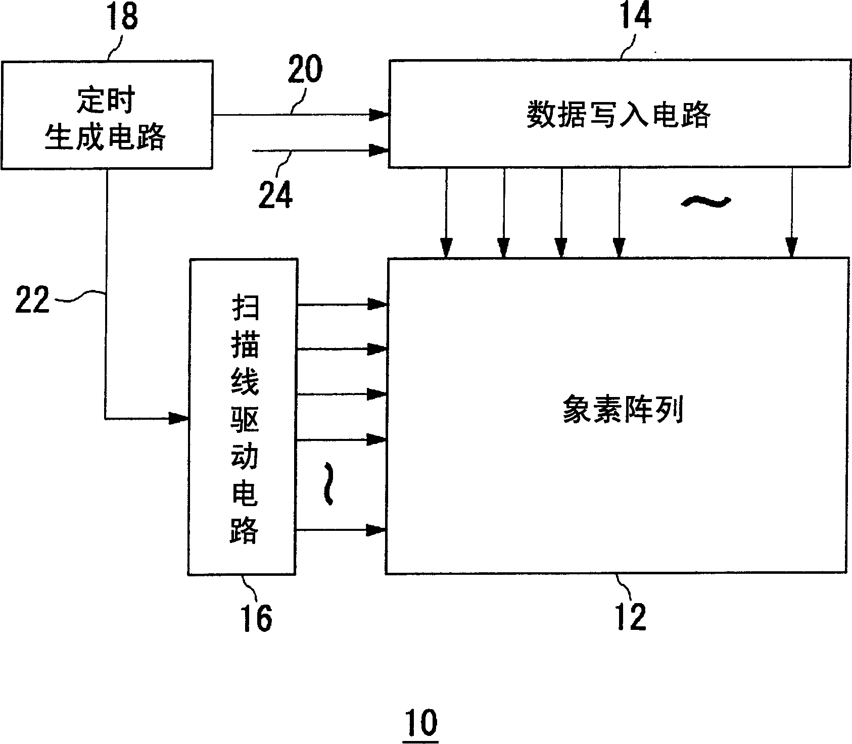
[0049] figure 1 The configuration of the display device 10 according to the embodiment is shown. The display device 10 includes a pixel array 12 made of liquid crystals arranged in a matrix, and a data writing circuit 14 for writing pixel values, that is, pixel data, to pixels in each row of the pixel array 12. 12 scan line drive circuit 16 for performing operations in the column direction, and timing generation circuit 18 for giving timing to write operations performed by data write circuit 14 and scan line drive circuit 16 .

[0050] The timing generation circuit 18 has a built-in PLL (Phase Lock Loop (Phase Lock Loop)) circuit. For the data writing circuit 14, a pulse equivalent to the number of pixels in the horizontal direction is generated from the horizontal synchronizing signal, and the speed is further doubled as a writing speed. Input clock 20 output. Also, a normal double-speed scan clock 22 is output to the scan line drive circuit 16 in the same manner. Image da...


PUM


Abstract

A hold-type display apparatus is more likely to suffer the deterioration in the visibility of moving images due to the blur effect, compared to an impulse-type display apparatus. A single frame period is divided into a first period and a second period. Pixel data to be written to a pixel are written in a concentrated manner in the first period during a frame period. At this time, a write value for the pixel is set to twice a value of the image data in order not to lower the brightness of the images as a whole. However, only if the doubled value exceeds a range that can be displayed, the remaining pixel data are written in the second period. Thus, the change in display brightness approximates the impulse-type display apparatus, so that the visibility of moving images is improved.

Description

technical field [0001] The present invention relates to display technology, in particular to a method for displaying animation in a hold-type display device, a display device using the method and a data writing circuit that can be used in the display device. Background technique [0002] With the progress of liquid crystal display (hereinafter referred to as LCD) and plasma display (hereinafter referred to as PDP), and they also function as thin, such display devices are being adopted from cathode ray tube (hereinafter referred to as PDP) in television receivers. known as CRT) to seize the dominant position. We believe this trend will accelerate further in the future. [0003] However, it has come to be known that in LCDs and PDPs (hereinafter referred to as LCDs, etc.), the quality of moving pictures deteriorates due to a display principle different from that of CRTs. That is, an LCD or the like is a so-called "hold type" display device, which uses a transistor as a selec...

Claims


Application Information

Patent Timeline
Patent Type & Authority Applications(China)
IPC IPC(8): G02F1/133G09F9/00G09G3/20G09G3/36H04N5/66
CPCG09G2320/106G09G3/3607G09G3/3611G09G3/20G09G2310/08G09G2320/0261G09G3/28G09G3/2022G09G3/2081G09G3/2003
Inventor 田冈峰树森幸夫池田贵司
Owner SANYO ELECTRIC CO LTD
Why Eureka
Try Eureka