Touch control pen ejection structure of portable computer device

A mobile computer and stylus technology, which is applied in the direction of electrical digital data processing, instruments, digital data processing components, etc., to ensure the effect of not easily slipping out of the pen slot

Inactive Publication Date: 2004-08-18
QUANTA COMPUTER INC
View PDF0 Cites 5 Cited by
  • Summary
  • Abstract
  • Description
  • Claims
  • Application Information

AI Technical Summary

Problems solved by technology

Most of the stylus provided in PDA or Pocket PC are made of plastic or metal, and there is no electronic device built into the stylus

Method used


Image

  • Touch control pen ejection structure of portable computer device
  • Touch control pen ejection structure of portable computer device
  • Touch control pen ejection structure of portable computer device

Examples


Embodiment Construction

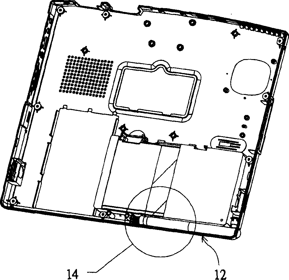
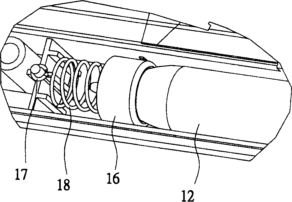
[0020] Please refer to Figure 1A , which shows the position diagram of the groove of the stylus pen according to a preferred embodiment of the present invention. The position of the stylus pen groove 10 can be in addition to the body of the mobile computer device ( Figure 1A As shown), it can also be in the liquid crystal module part, and the mobile computer device includes a notebook computer, a tablet computer, etc. In this embodiment, a notebook computer is used as an example for illustration, but it is not intended to limit the scope of application of the present invention. In the design of the pen holder 10 , the design of the switch structure is required to fix the stylus in the pen holder 10 . In addition to the switch structure design, a pop-up structure can also be designed to provide a more convenient way to remove the stylus from the pen slot. Figure 1B The pop-up structure of the pen tray according to a preferred embodiment of the present invention is shown. Th...


PUM


Abstract

The invention discloses an ejection arrangement for touch control pens adapted for a mobile computer device, which is mounted on the bottom of a pen groove, wherein the ejection arrangement comprises a resilient device with one end mounted to the bottom of a pen groove for providing the force for touch control pen ejection, and a pen cap with one end connected with the resilient device and an opening for bearing the pen point.

Description

technical field [0001] The invention relates to a pop-up structure of a touch pen, in particular to a pop-up structure of a touch pen of a mobile computer device. Background technique [0002] With the rapid advancement of personal computer manufacturing technology, computers that could only be placed on the table (so-called desktop computers, Desktop PC) have now derived various types of computers, such as notebook computers (Notebook PC), palm-sized Computer (Pocket PC), Personal Digital Assistant (Personal Digital Assistant, PDA, for example: Palm OS PDA), and various computer devices that provide Internet access. [0003] These above-mentioned various computer devices, because most of these devices are designed smaller than desktop computers, and do not have the keyboard input function or need an external keyboard to provide the keyboard input function. Therefore, most of these mobile computer devices provide handwriting input or touch functions. For example, a PDA may...

Claims


Application Information

Patent Timeline
Patent Type & Authority Applications(China)
IPC IPC(8): G06F1/16
Inventor 杨国昌篮世华
Owner QUANTA COMPUTER INC
Why Eureka
Try Eureka