
Intermediate driving axle for propelling ship

An intermediate shaft and longitudinal axis technology, applied in the field of intermediate drive shafts, can solve the problems of high price, inconvenience and bulkiness

Inactive Publication Date: 2004-08-25
MAN B & W DIESEL AS
View PDF0 Cites 0 Cited by
  • Summary
  • Abstract
  • Description
  • Claims
  • Application Information

AI Technical Summary

Problems solved by technology

These measures have their disadvantages: they are either expensive, inconvenient, and / or the engine equipment becomes larger and heavier

Method used


Image

  • Intermediate driving axle for propelling ship
  • Intermediate driving axle for propelling ship
  • Intermediate driving axle for propelling ship

Examples


Embodiment Construction

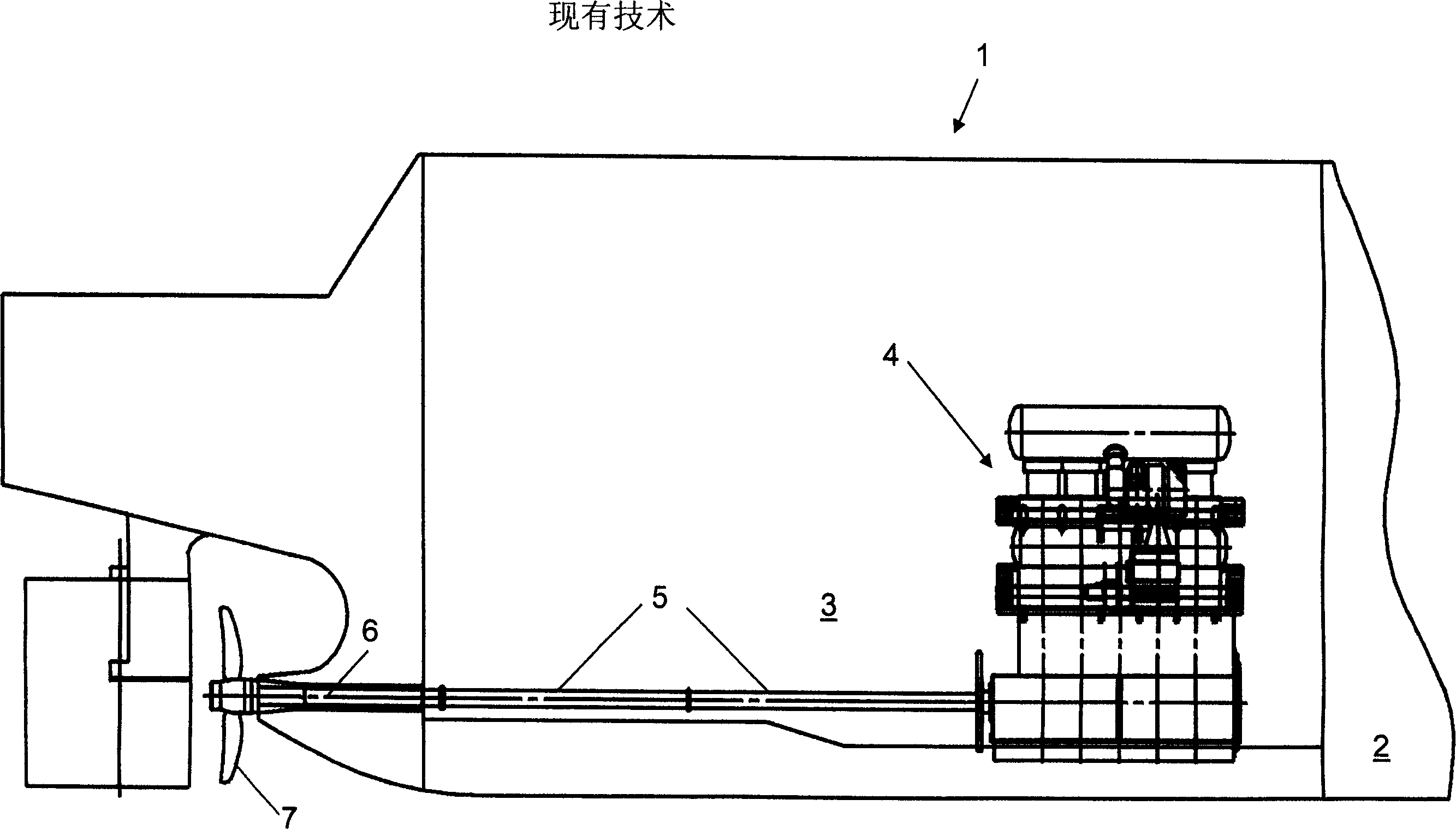
[0027] figure 1 A prior art hull 1 of a vessel with a cargo hold 2 and an engine room 3 is shown. A crosshead type 5-cylinder two-stroke engine 4 is located just behind the wall separating the engine compartment 3 from the cargo compartment 2 .

[0028] A solid and relatively long intermediate shaft 5 connects the output shaft of the engine 4 and the propulsion shaft 6 which drives the propeller 7 . The intermediate shaft has high torsional flexibility due to its long length. In this design of the ship's drive system, the level of overstress of the intermediate shaft due to torsional resonance is rarely the case.

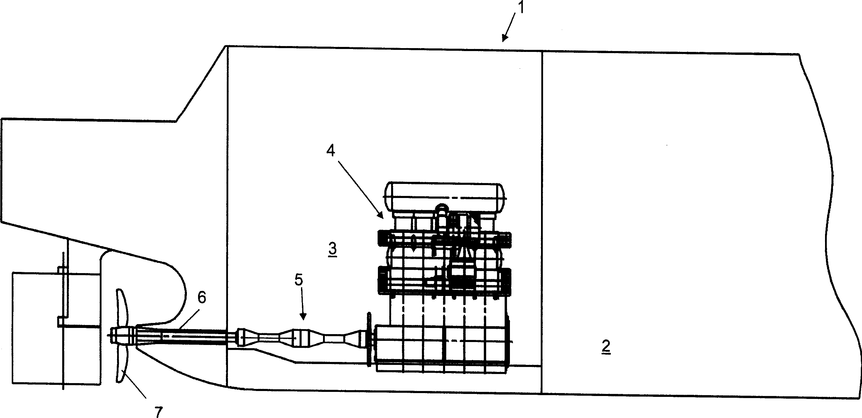
[0029] figure 2 Shown is a hull 1 of a vessel with a cargo hold 2 and an engine room 3 according to an embodiment of the invention. engine compartment 3 ratio figure 1 The engine compartment of the embodiment shown in is shorter so that a larger cargo compartment 2 is possible even with other parameters being the same.

[0030] A large crosshead-type 5-cylind...


PUM


Abstract

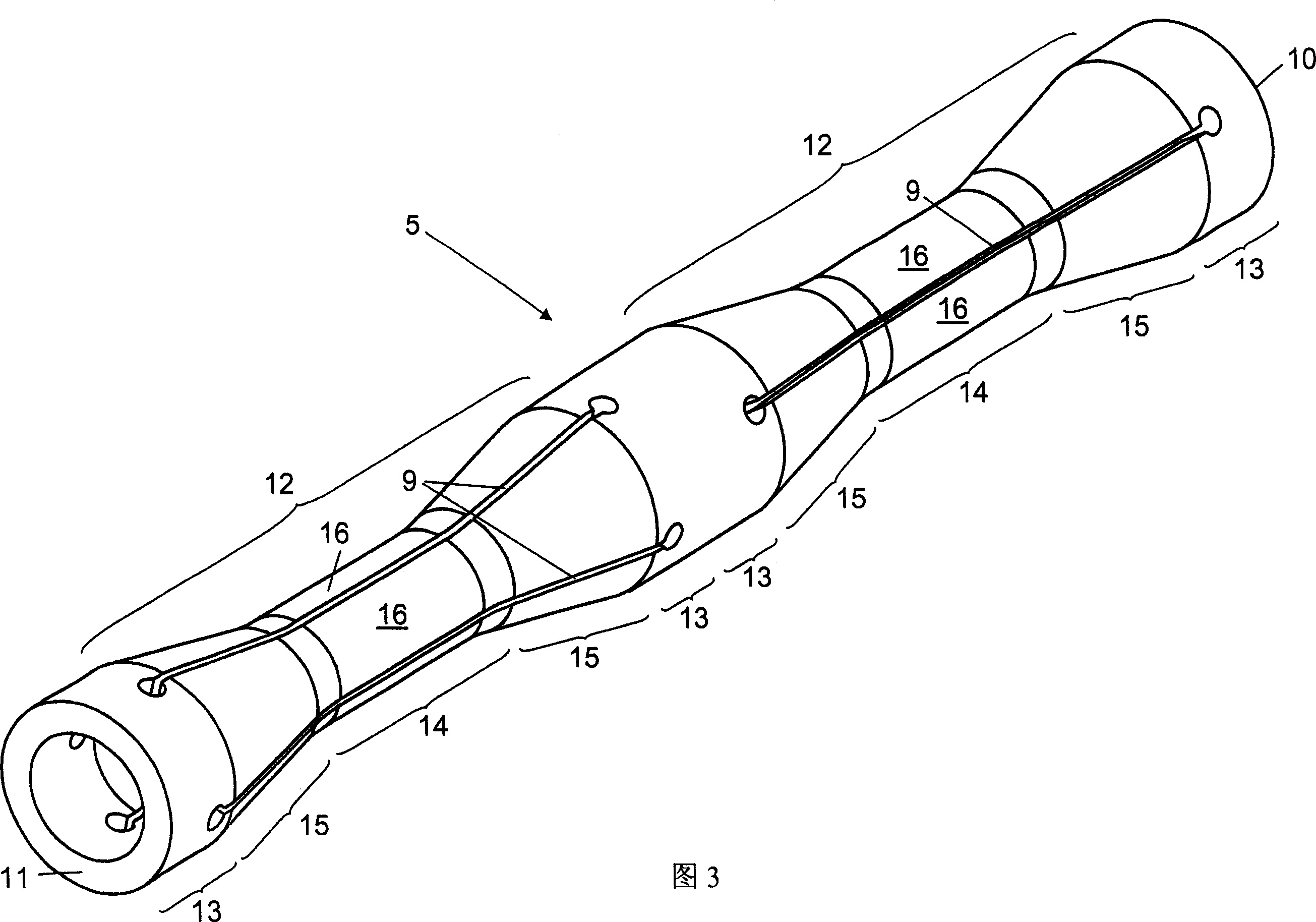
The present invention relates to an intermediate drive shaft for ship propelling system, in particular, it is a ship propelling system including a large double-stroke internal combustion engine. Said internal combustion engine is connected with a propelling shaft by means of an intermediate shaft, and said intermediate shaft, at least its a portion, is formed from two or several components which are radially and symmetrically distributed along the axis of intermediate shaft and parallelly extended.

Description

technical field [0001] The present invention relates to an intermediate drive shaft for a ship's propulsion system, and more particularly to a ship's propulsion system comprising a high capacity two-stroke internal combustion engine connected to the propulsion shaft via an intermediate shaft. [0002] The countershaft design of the present invention is designed to improve the control of shaft stresses caused by torsional resonance of the countershaft caused by engine-generated excitation. The main excitation comes from the moment of combustion pressure and the internal force of rotating and reciprocating objects. These forces are properties of the engine. These force-increasing trends, referred to as pressures, indicate a reduction in the maximum continuous load index in order to reduce consumption of a particular fuel. These trends all lead to an increase in the excitation torque and an increase in the velocity of the single-node torsional resonance. These questions apply ...

Claims


Application Information

Patent Timeline
Patent Type & Authority Applications(China)
IPC IPC(8): B63H23/34
Inventor 皮·瑞得弗德瑞克·拉·克劳克
Owner MAN B & W DIESEL AS
Learn More