Rainwater drainage passage for road and its construction process

A drainage channel and construction method technology, applied in water/sewage treatment, chemical instruments and methods, water/sludge/sewage treatment, etc., can solve problems such as time-consuming and labor-intensive cleaning work, traffic interference, etc. Large water section, simple and convenient installation

Inactive Publication Date: 2004-09-08
SHANGHAI MUNICIPAL ENG DESIGN INST GRP
View PDF0 Cites 6 Cited by
  • Summary
  • Abstract
  • Description
  • Claims
  • Application Information

AI Technical Summary

Problems solved by technology

The cleaning work is time-consuming and laborious, and often takes up the road for a long time, which also brings great disturbance to the traffic

Method used


Image

  • Rainwater drainage passage for road and its construction process
  • Rainwater drainage passage for road and its construction process
  • Rainwater drainage passage for road and its construction process

Examples


Embodiment Construction

[0010] The present invention will be further described below in conjunction with the accompanying drawings and embodiments.

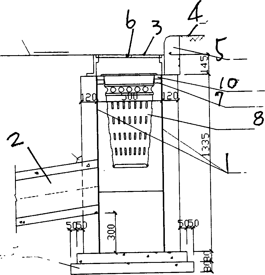
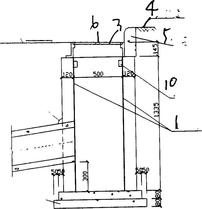
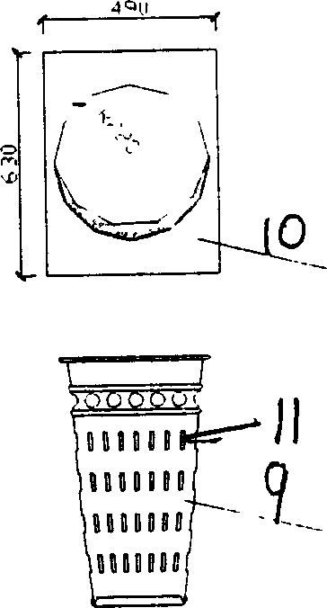
[0011] The present invention is a road rainwater drainage channel, which mainly includes a water well 1, the water well is arranged at the end of the side stone 5 of the sidewalk 4, a cross channel 2 connected with the water well 1, a water inlet at the end of the water well, and The water outlet is provided with a cover plate 3, and the cover plate is provided with a drainage hole 6. It is different from the prior art in that: a backing plate seat 7 is provided at the water inlet, and a filter bucket 8 is installed below the backing plate seat to implement intermediate filtration. The bucket 8 has an opening and a bucket body 9. A backing plate 10 matched with the backing plate seat at the water inlet is provided at the opening. The bucket body has a number of filter holes 11. The filter bucket is made of PVC plastic, which is relatively light. It is e...


PUM


Abstract

The rainwater drainage passage for road features that its water inlet is provided with one bottom plate seat and one filtering bin under the bottom plate seat. The PVC made garbage filtering bin set in the gully can collect deposited garbage and the deposited garbage may be cleaned through dumpage easily. The present invention is simple, low in cost, and suitable for use in city road.

Description

Technical field: [0001] The invention relates to the technical field of road drainage, in particular to a road rainwater drainage channel and a construction method thereof. Background technique: [0002] In urban road engineering, the problems of desilting the water inlet of the road surface and dredging the drainage pipes will be encountered. At present, no garbage filter bucket is provided in the usual rainwater intake, and only cast iron grate covers are used. Due to the large opening of the grate cover, a large amount of road rubbish will fall into the rainwater well, sink in the rainwater well and in the rainwater pipe. Every once in a while, it is necessary to clean up the bottom garbage in the rainwater well with a digging spoon. The cleaning work is time-consuming and labor-intensive, and it often takes up the road for a long time and brings great disturbance to the traffic. Invention content: [0003] The purpose of the present invention is to provide a road ra...

Claims


Application Information

Patent Timeline
Patent Type & Authority Applications(China)
IPC IPC(8): E03F5/14
Inventor 温学钧张瑜
Owner SHANGHAI MUNICIPAL ENG DESIGN INST GRP
Why Eureka
Try Eureka