
Natural ventilating and mechanical ventilating dual-purpose system for continuous-building type greenhouse

A technology of natural ventilation and mechanical ventilation, applied in greenhouse cultivation, horticulture, climate change adaptation and other directions, can solve the problems of difficult to ensure sealing, high operating cost, large opening of windows, etc., to achieve both ventilation performance and economical efficiency Effect

Inactive Publication Date: 2004-09-15
ZHEJIANG UNIV
View PDF0 Cites 3 Cited by
  • Summary
  • Abstract
  • Description
  • Claims
  • Application Information

AI Technical Summary

Problems solved by technology

However, in order to prevent short circuit caused by air leakage during mechanical ventilation, the greenhouse is required to have better airtightness, which is easy to form heat accumulation inside the greenhouse and increase the ventilation operating load, and the daily operation is very dependent on electricity, and the overall operating cost is relatively high.
[0005] Conventional natural ventilation adopts rolling film windows or rack and pinion driven windows. Rolling film windows are usually used in film greenhouses. The opening of the window is relatively large, but the sealing is not easy to guarantee, and it is difficult to use it with the mechanical ventilation system.
The flap-type ventilation window pushes the window tightly through the gear rack driven by the mechanism to achieve the purpose of sealing and closing. The sealing performance is guaranteed, but the opening is small, and the opening angle usually does not exceed 45 degrees. The cost of the mechanism is relatively high, and the overall ventilation poor efficiency
[0006] The operating cost of natural ventilation is low, but it is not easy to ensure the ventilation performance for a long time; the performance of mechanical ventilation can meet the production and use requirements, but the operation cost is high for long-term operation

Method used


Image

  • Natural ventilating and mechanical ventilating dual-purpose system for continuous-building type greenhouse
  • Natural ventilating and mechanical ventilating dual-purpose system for continuous-building type greenhouse
  • Natural ventilating and mechanical ventilating dual-purpose system for continuous-building type greenhouse

Examples


Embodiment Construction

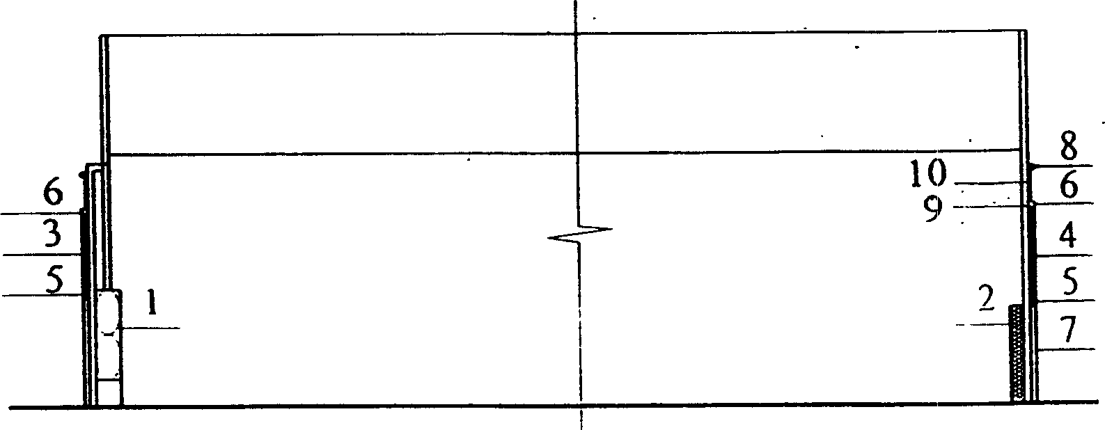
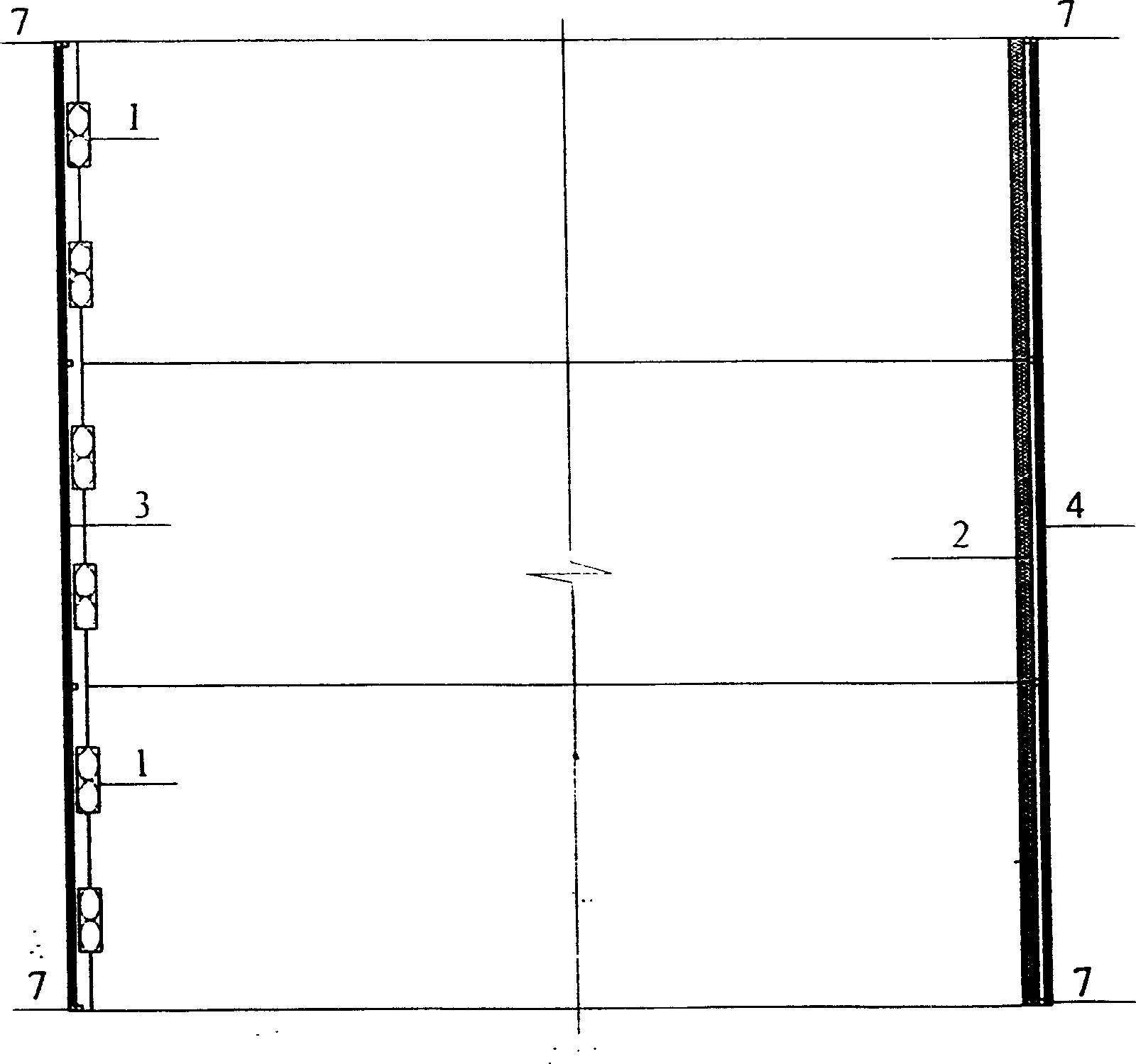
[0017] Such as figure 1 , figure 2 As shown, it includes: fan 1, wet curtain 2, natural ventilation window 3 on the side of the fan, natural ventilation window 4 on the side of the wet curtain, sliding window mechanism of the natural ventilation window, and sealing device of the natural ventilation window. Several fans 1 are installed at the bottom of one end or side of the greenhouse, natural ventilation windows 3 on the fan side are installed on the upper guide rail fixing rod 7 of the fan 1, and wet curtains 2 are installed at the other corresponding end or side bottom of the greenhouse The natural ventilation window 4 on the side of the wet curtain is installed on the guide rail fixing rod 7 on the top of the wet curtain 2; the natural ventilation window 3 on the fan side and the natural ventilation window 4 on the wet curtain side are respectively equipped with a sliding window mechanism and Sealing means.

[0018] Such as figure 1 , image 3 As shown, the sliding wi...


PUM


Abstract

The present invention relates to a natural ventilation and mechanical ventilation system for series greenhouse system, and is characterized by that several blower fans are mounted on the bottom portion of one end face or side face of the greenhouse, a natural ventilation window is mounted on the upper guideway fixing bar of blower fan, a wet curtain is mounted on the bottom portion of another correspondent end face or side face of the greenhouse, on the guideway fixing bar of upper portion of the wet curtain a natural ventilation window is mounted, said natural ventilation windows of blower fan side and wet curtain side are respectively equipped with window-sliding mechanism of window body and sealing device. After the natural ventilation window of blower fan side of closed, it can make mechanical ventilation, and after all the natural ventilation windows are closed, it can utilize the wet curtain to lower temperature.

Description

Technical field [0001] The invention relates to a device system of a multi-span greenhouse ventilation system, in particular to a multi-span greenhouse dual-purpose system for natural ventilation and mechanical ventilation. Background technique [0002] At present, the known multi-span greenhouse ventilation system adopts natural ventilation or mechanical ventilation. In actual production and use, only one of the ventilation methods is selected. These two ventilation methods are not available in the greenhouse system at the same time. [0003] The use of natural ventilation is based on the principle of wind pressure and heat pressure. Under many climatic conditions, such as when the outside is windy or the temperature is not too high, a better ventilation effect can be achieved. Its usual operating cost is low and maintenance is convenient. However, it is easily affected by external natural climate conditions and limited by effective ventilation distance and other conditions...

Claims


Application Information

Patent Timeline
Patent Type & Authority Applications(China)
IPC IPC(8): A01G9/24
CPCY02A40/25
Inventor 应义斌王剑平俞永华
Owner ZHEJIANG UNIV
Learn More