
Universal Windmill

A technology of windmills and blades, applied in the field of wind power application equipment

Inactive Publication Date: 2004-09-15
李洪泽
View PDF0 Cites 5 Cited by
  • Summary
  • Abstract
  • Description
  • Claims
  • Application Information

AI Technical Summary

Problems solved by technology

The shaft is located in the center of the bracket

Method used


Image

  • Universal Windmill
  • Universal Windmill
  • Universal Windmill

Examples


Embodiment

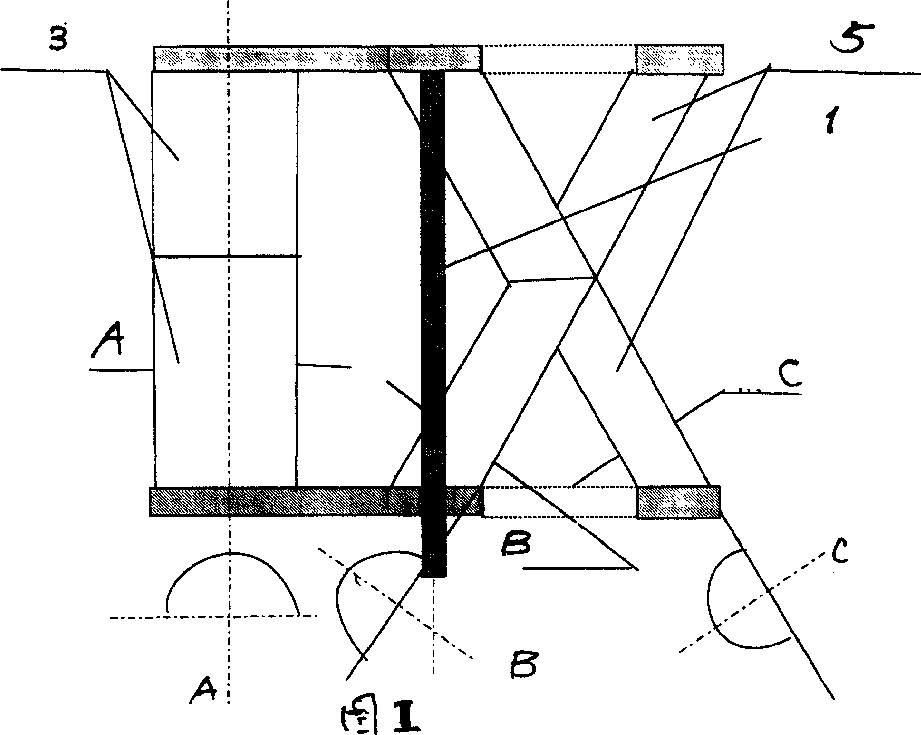
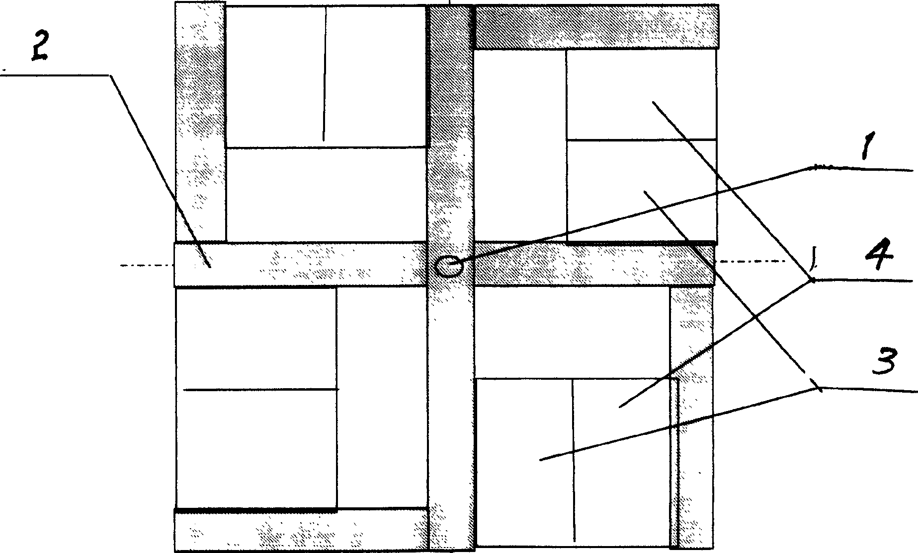
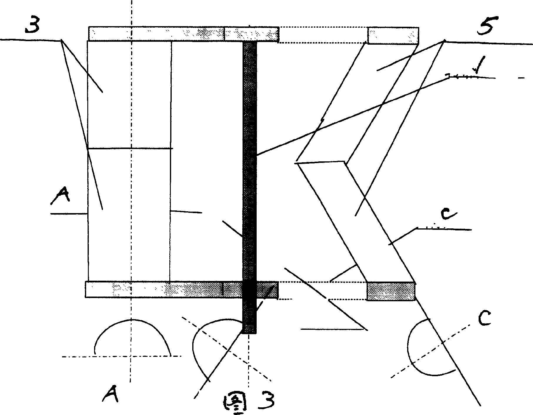
[0025] See Figure 1, figure 2 , be nailed into the upper and lower brackets 2 of two crosses with long wooden strips, then do support and fix with thin wooden strips, at the top of each wooden strip of support 2, horizontally fix wooden strips, make support 2.

[0026] Make 8 semi-cylinders with thin iron sheets, make blades, cross in twos (note the uneven surface) and be fixed on the support 2. After the upper and lower brackets 2 are punched (the upper bracket should not be pierced), penetrate the rotating shaft 1, and the universal windmill is successfully manufactured.


PUM


Abstract

The invention is a kind of universal wind wheel; it refers to a kind of wind power application device. The wind wheel is made up of blades, bracket and shaft. The blade is arc type, it is divided into convexity and concave surfaces, the two surfaces are crossed, and they are set on the bracket. The shaft is in the middle of bracket. The character of the wind wheel is: 1. the universal wind wheel has no demands to wind direction. 2. if hope to enhance the wind wheel power, it only needs to enlarge the length and the width of the blade (at the same time, increases the size of bracket), it is very convenient. The invention can be used in: 1. develops into a wind power flying organ, car or ship. 2. it can be used in wind power electricity generating station. 3. it can be produced into water wheel machine in electricity station without dam, or tide electricity generating. 4. it can be produced into kids toy.

Description

technical field [0001] The invention relates to a wind power application device. Background technique [0002] Wind power is a ubiquitous energy source with great application value in nature. However, the previous windmills were based on the working principle of fan blades. Limited by the wind direction, windmills must face the wind to rotate. This invention is based on the working principle of fluid mechanics. , without wind direction restriction. Contents of the invention [0003] 1. Windmill structure: [0004] The windmill consists of three parts: blades, brackets and shafts. [0005] The blades are arc-shaped, divided into concave and convex sides, crossed in pairs, and mounted on the bracket. The rotating shaft is located in the center of the bracket. [0006] 2. Working principle [0007] Because the blade is arc-shaped, when the side of the blade is facing the wind, the flow velocity on the concave surface is basically unchanged, while the flow velocity on the...

Claims


Application Information

Patent Timeline
IPC IPC(8): F03D3/06
CPCY02E10/74
Inventor 李洪泽
Owner 李洪泽
Learn More